Step 2
Turn off the circuit breaker to the power supply.
Step 3
For easier installation, plug the power cable into the inlet on power supply slot 1 first.
Step 4
Then insert the power supply cable into the power supply in slot 0 on the right.
Step 5
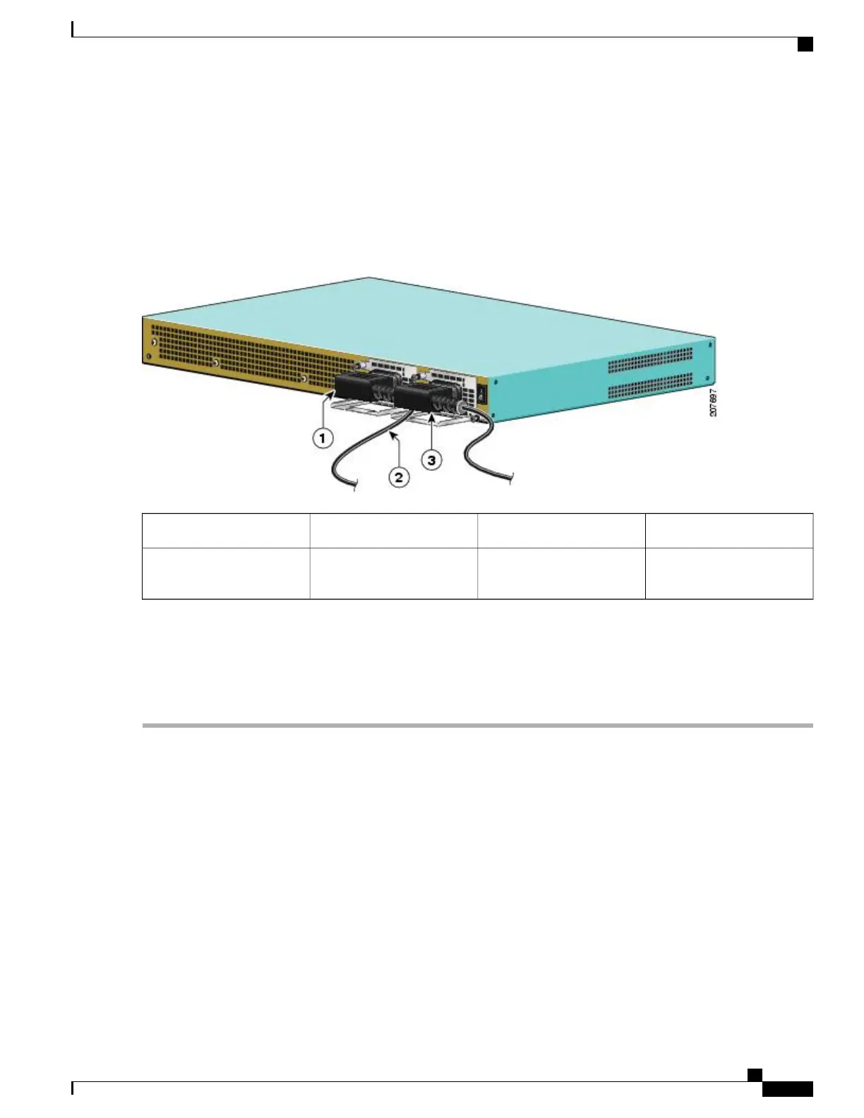
Make certain that the AC power cords are positioned as shown in the following image.
Figure 217: Correct Position of the Cisco ASR 1001 Router AC Power Supply Cables
AC power supply in PS13AC power supply in PS01
——
Position of power supply
cable from PS0
2
Step 6
Plug the AC power supply cables into the AC power source.
Step 7
Turn on the AC breaker.
Step 8
Turn the Standby switch to On (|) on the chassis.
Step 9
The power supply LED illuminates green.
What to Do Next
This completes the procedure for connecting AC input power.
Removing AC Power Supply from the Cisco ASR 1001 Router
This section describes how to remove an AC power supply from the Cisco ASR 1001 Router. The Cisco ASR
1001 Router has two power supply slots, power supply slot 1 (PS1) next to the Standby switch and power
supply slot 0 (PS0) to the left, as shown in the following image.
Follow these steps to remove an AC power supply from the Cisco ASR 1001 router:
Cisco ASR 1000 Series Router Hardware Installation Guide
449
Cisco ASR 1001 Router Overview and Installation
Removing AC Power Supply from the Cisco ASR 1001 Router
 Loading...


