EasyManuals Logo

Cisco ASR 1002-X Hardware Installation Guide

Cisco ASR 1002-X
702 pages
To Next Page IconTo Next Page
To Previous Page IconTo Previous Page
Page #611 background imageLoading...
Page #611 background image
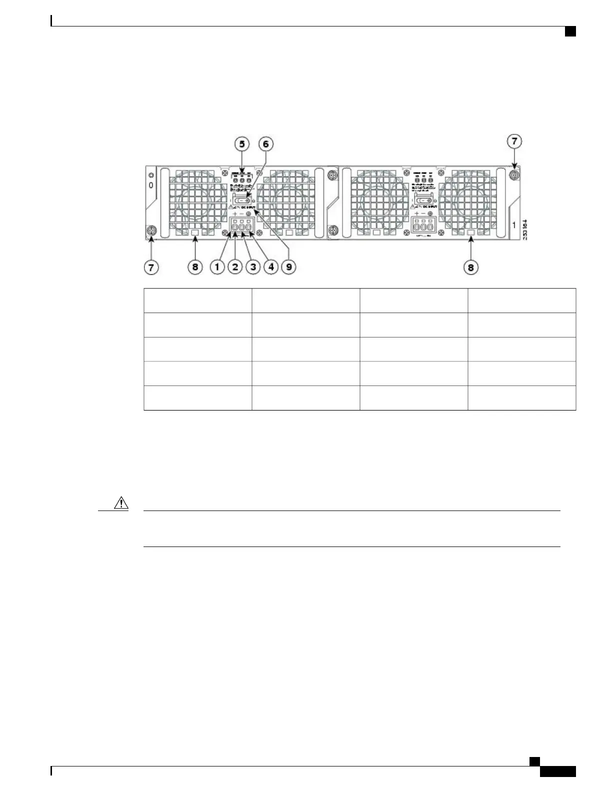
The following figure shows the +24 VDC power supply and components for the Cisco ASR 1002 Router.
Figure 284: Cisco ASR 1002 Router +24 VDC Power Supply
Standby/On switch6+24 VDC terminal block1
Captive fastener7Positive (+) lead2
Power supply tabs8Negative (-) lead3
+27 VDC INPUT label9Ground (GND) lead4
Power supply LEDs5
Removing the +24 VDC Power Supply from Cisco ASR 1002 Router
Before you can remove a +24 VDC power supply from the Cisco ASR 1002 Router, you must remove input
power going to the power supply.
Make certain that the chassis ground lead wire is connected before you begin removing and installing the
power supply.
Caution
To remove the +24 VDC power supply from the Cisco ASR 1002 Router, follow these steps:
Cisco ASR 1000 Series Router Hardware Installation Guide
577
Removing and Replacing FRUs from the Cisco ASR 1000 Series Routers
Removing and Replacing a +24 VDC Power Supply in Cisco ASR 1002 Router

Table of Contents

Other manuals for Cisco ASR 1002-X

Questions and Answers:

Question and Answer IconNeed help?

Do you have a question about the Cisco ASR 1002-X and is the answer not in the manual?

Cisco ASR 1002-X Specifications

General IconGeneral
Form FactorRack-mountable
Rack Units2RU
Integrated ServicesYes
Maximum Memory16 GB
Built-in Gigabit Ethernet Ports6
Input Voltage100-240 VAC
Operating Temperature32 to 104°F (0 to 40°C)
RedundancyPower supply redundancy
Network Interface ModulesUp to 4 SPA/SIP slots
Embedded Services Processor (ESP)ESP-20
Maximum Packet per Second (PPS)15 Mpps
Height3.5 inches
Fixed Ports6 GE ports
Memory4 GB (default), 16 GB (maximum)
Power SupplyDual power supplies (AC or DC)
Dimensions (H x W x D)3.5 x 17.5 x 19.0 in (8.9 x 44.5 x 48.3 cm)

Related product manuals