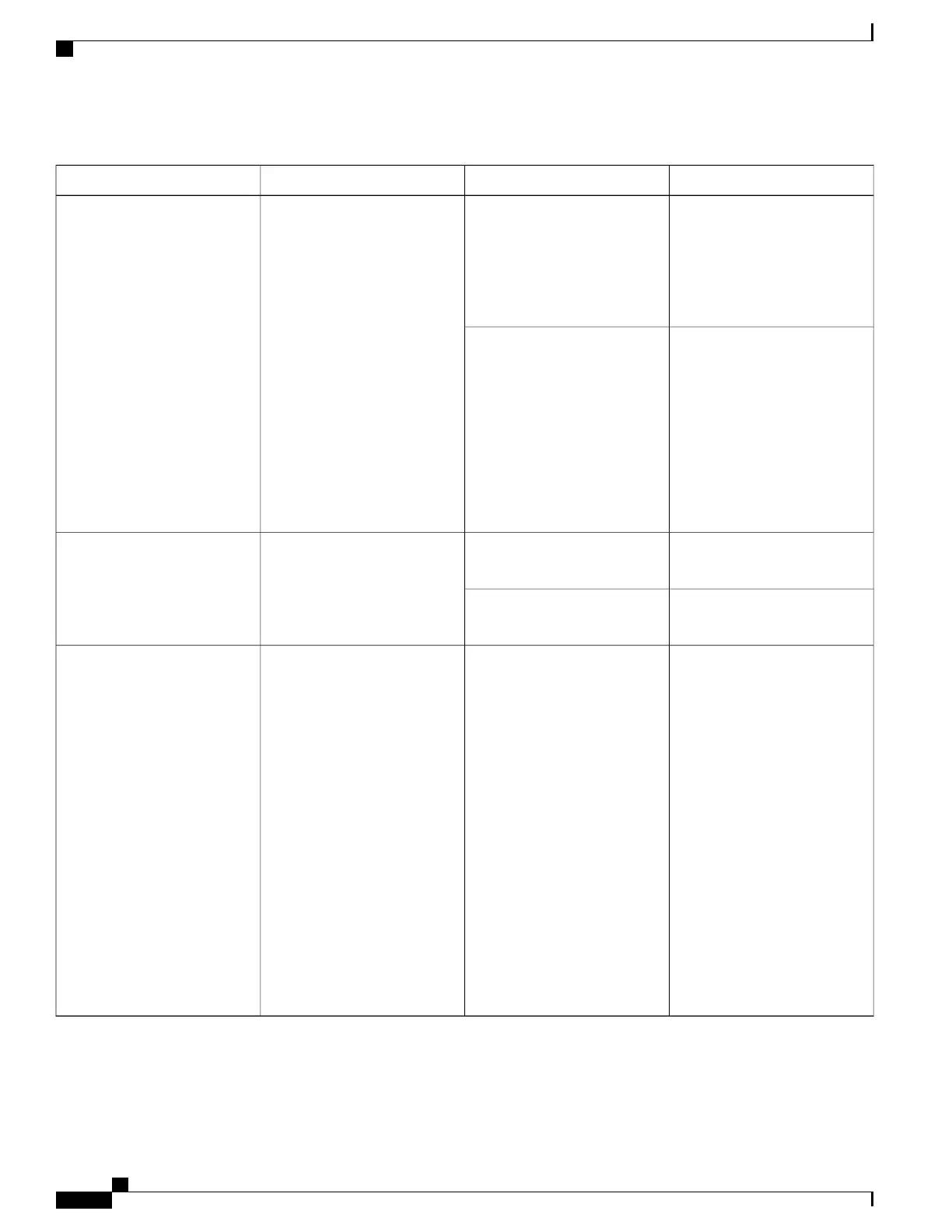
Table 71: Cisco ASR 1002-X Router
–
48 VDC Power Supply LEDs
DescriptionColorLEDLED Label
The LED turns green to signal
that the DC power supply input
voltage is greater than 43.5VDC
at turn-on and remains green
until the level of 39 VDC is
reached.
GreenA bi-color LED indicates the
presence of input voltage
INPUT OK
The LED turns amber if the
power supply turns off due to
low input voltage (falls below
39VDC) and indicates that a
hazard (voltage on the terminal
block) is still present. The LED
remains amber and is active
until around 20 V +/-5 V. If the
input is below 15 V, the LED is
not illuminated
Amber
The LED turns green when all
fans are operational.
GreenA bi-color LED indicates power
supply fan status
FAN OK
The LED turns red when a fan
failure is detected.
Red
When the LED is off, it signals
that the DC output voltage is
within the normal operating
range. Output voltage between
the minimum limit and
maximum limit will not create
an Output Fail alarm, but output
voltages below the minimum
limit or above the maximum
limit will create an Output Fail
alarm.
Led turns red to indicate that the
DC output is out of the
specified range.
When you turn on the power
supply, the LED turns red for
two to three seconds to test the
LED operation before going off.
RedPower supply activityOUTPUT FAIL
Cisco ASR 1000 Series Router Hardware Installation Guide
326
Cisco ASR 1002-X Router Overview and Installation
Power Supplies in the Cisco ASR 1002-X Router
 Loading...


