EasyManuals Logo

Cisco ASR 1002-X Hardware Installation Guide

Cisco ASR 1002-X
702 pages
To Next Page IconTo Next Page
To Previous Page IconTo Previous Page
Page #262 background imageLoading...
Page #262 background image
the DC input wiring. The connection order is negative (), positive (+), and GND. The DC power supply is
secured into the system chassis with two captive screws mounted on the faceplate.
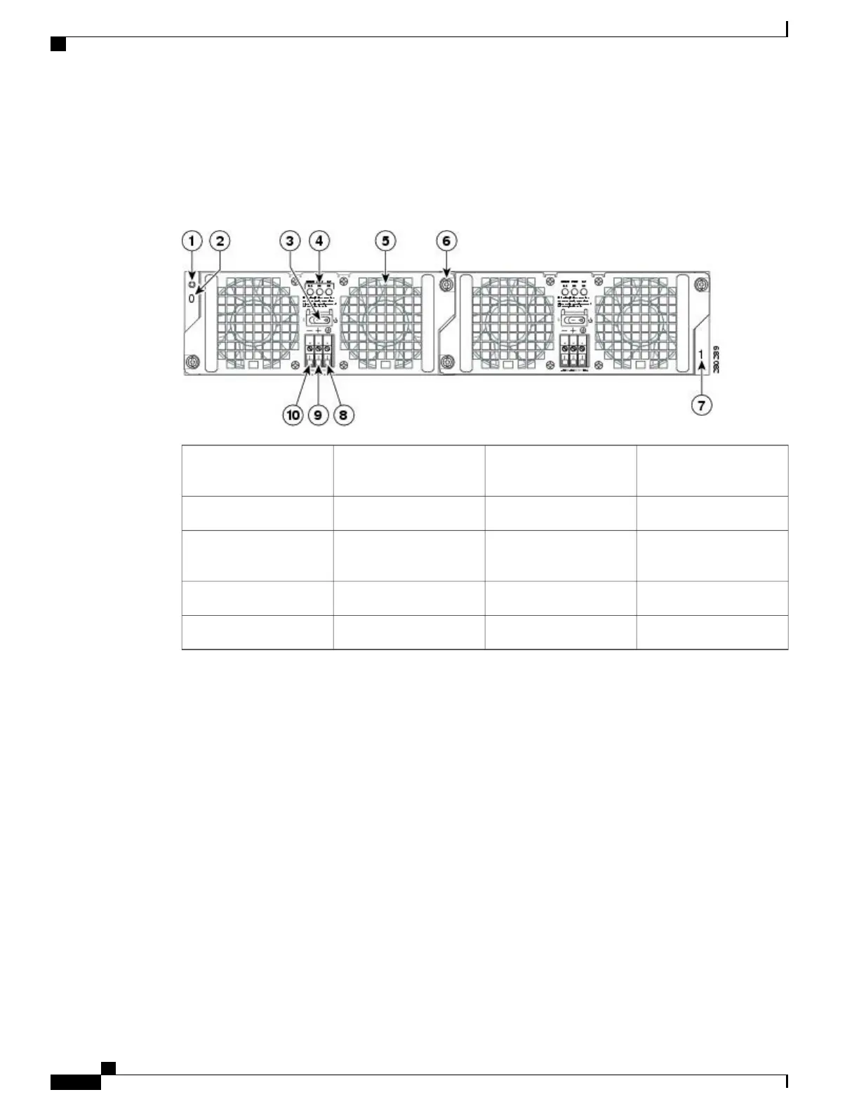
The following image shows the 48 VDC Power Supply for the Cisco ASR 1002 Router.
Figure 85:
48 VDC Power Supply for the Cisco ASR 1002 Router
Power supply captive
installation screw
6Chassis ESD socket1
Power supply slot 1 label7Power supply slot 0 label2
Ground lead8Power supply switch
Standby/On (|)
3
Positive lead9Power supply LEDs4
Negative lead10Fan5
The Cisco ASR 1002 Router 48 VDC power supply LEDs are described in the following table.
Cisco ASR 1000 Series Router Hardware Installation Guide
228
Cisco ASR 1002 Router Overview and Installation
Power Supplies in the Cisco ASR 1002 Router

Table of Contents

Other manuals for Cisco ASR 1002-X

Questions and Answers:

Question and Answer IconNeed help?

Do you have a question about the Cisco ASR 1002-X and is the answer not in the manual?

Cisco ASR 1002-X Specifications

General IconGeneral
Form FactorRack-mountable
Rack Units2RU
Integrated ServicesYes
Maximum Memory16 GB
Built-in Gigabit Ethernet Ports6
Input Voltage100-240 VAC
Operating Temperature32 to 104°F (0 to 40°C)
RedundancyPower supply redundancy
Network Interface ModulesUp to 4 SPA/SIP slots
Embedded Services Processor (ESP)ESP-20
Maximum Packet per Second (PPS)15 Mpps
Height3.5 inches
Fixed Ports6 GE ports
Memory4 GB (default), 16 GB (maximum)
Power SupplyDual power supplies (AC or DC)
Dimensions (H x W x D)3.5 x 17.5 x 19.0 in (8.9 x 44.5 x 48.3 cm)

Related product manuals