SUMMARY STEPS
1.
Locate the threaded ear holes on the rear side of the chassis. Make certain that you hold the rear rack-mount
bracket with the ear and holes facing outward and towards the rear of the chassis.
2.
Position the rear rack-mount bracket top hole with the chassis top hole from the back.
3.
Insert and tighten the screws on one side.
4.
Repeat Step 1 through Step 3 on the other side of the chassis. Use the remaining screws to secure the rear
rack-mount brackets to the chassis.
DETAILED STEPS
Step 1
Locate the threaded ear holes on the rear side of the chassis. Make certain that you hold the rear rack-mount bracket with
the ear and holes facing outward and towards the rear of the chassis.
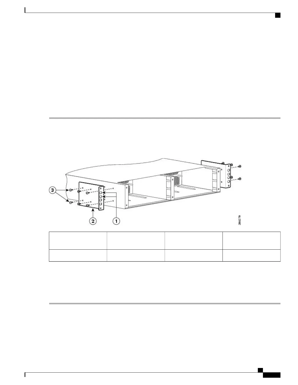
The following image shows where to attach the rear rack-mount brackets to the Cisco ASR 1002-F Router.
Figure 128: Attaching the Rear Rack-Mount Brackets to the Cisco ASR 1002-F Router
Rear rack-mount bracket
screws
3Rear rack-mount bracket ear
and holes
1
——
Rear rack-mount bracket2
Step 2
Position the rear rack-mount bracket top hole with the chassis top hole from the back.
Step 3
Insert and tighten the screws on one side.
Step 4
Repeat Step 1 through Step 3 on the other side of the chassis. Use the remaining screws to secure the rear rack-mount
brackets to the chassis.
What to Do Next
This completes the steps for attaching the rear rack-mount brackets to the Cisco ASR 1002-F Router.
Cisco ASR 1000 Series Router Hardware Installation Guide
295
Cisco ASR 1002-F Router Overview and Installation
Chassis Rear Rack-Mount Brackets
 Loading...


