Captive installation screw6AC power supply slot 0
label
2
AC power supply slot 1
label
7AC power supply On (|)
/Off (O) switch
3
AC power inlet8AC power supply LEDs4
To connect AC power to the Cisco ASR 1002-F Router, follow these steps:
SUMMARY STEPS
1.
At the rear of the router, check that the power switch is in the Off (O) position.
2.
Insert the AC power cable into the power supply AC inlet.
3.
To ensure that the AC power cord does not interfere with other cables or wires, dress the AC power cable
in one of the following ways:
4.
Plug the AC power supply cable into the AC power source.
DETAILED STEPS
Step 1
At the rear of the router, check that the power switch is in the Off (O) position.
Step 2
Insert the AC power cable into the power supply AC inlet.
Step 3
To ensure that the AC power cord does not interfere with other cables or wires, dress the AC power cable in one of the
following ways:
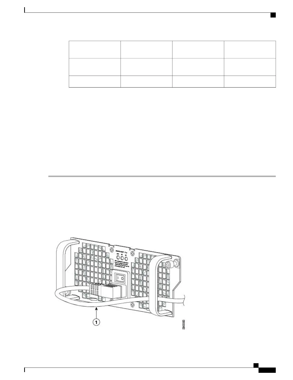
a) Leave a small service loop in the AC power cord from the inlet and secure the power cord through the AC power
supply handle as shown in the following image.
Figure 138: Cisco ASR 1002-F Router AC Power Supply in Slot 1 with Power Cord
Cisco ASR 1000 Series Router Hardware Installation Guide
309
Cisco ASR 1002-F Router Overview and Installation
Connecting AC Input Power to the Cisco ASR 1002-F Router
 Loading...


