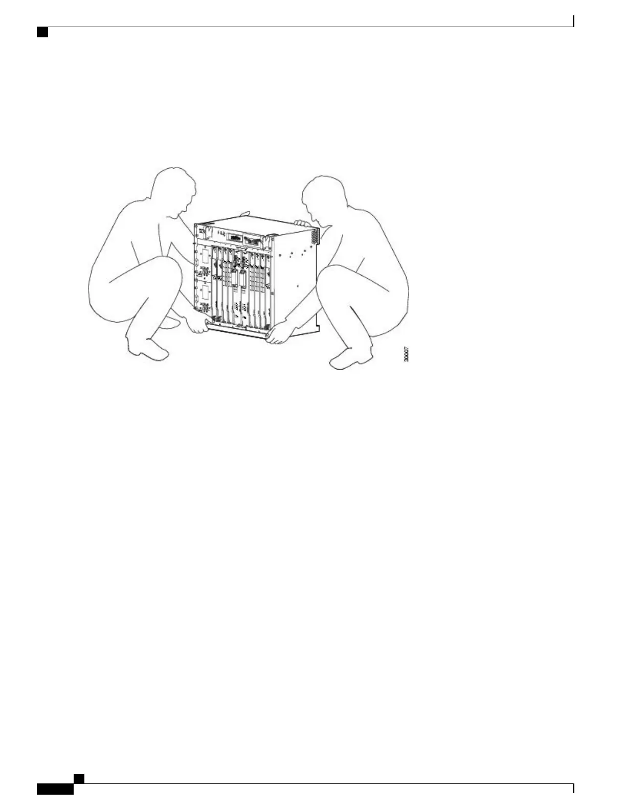
At least two people are required to lift the chassis onto a tabletop or platform. To prevent injury, keep your back straight
and lift with your legs, not your back. Statement 164
Figure 151: Lifting the Chassis
The chassis in the image does not represent the Cisco ASR 1002-X Router.
Step 3
Attach the front rack mount brackets. Locate the threaded holes in the front sides of the chassis (first holes beyond the
vent holes).
Step 4
Align the front rack mount bracket to one side of the chassis.
Step 5
Insert and tighten the black screws that shipped with the chassis on one side.
Step 6
Repeat Step-2 through Step-3 on the other side of the chassis. Use all the screws to secure the rack mount brackets to
the chassis.
The chassis rack mount brackets must be installed first so that you can attach the cable management brackets
to the chassis rack mount brackets after the chassis is installed in the rack.
Note
Step 7
Gather the two cable management brackets and screws shipped with your chassis. Attaching the Cable Management
Bracket, on page 345 shows the cable management brackets attached on the front of the Cisco ASR 1002-X Router.
Cisco ASR 1000 Series Router Hardware Installation Guide
334
Cisco ASR 1002-X Router Overview and Installation
Equipment Shelf or Tabletop Installation Procedure
 Loading...


