EasyManuals Logo

Cisco ASR 1002-X Hardware Installation Guide

Cisco ASR 1002-X
702 pages
To Next Page IconTo Next Page
To Previous Page IconTo Previous Page
Page #544 background imageLoading...
Page #544 background image
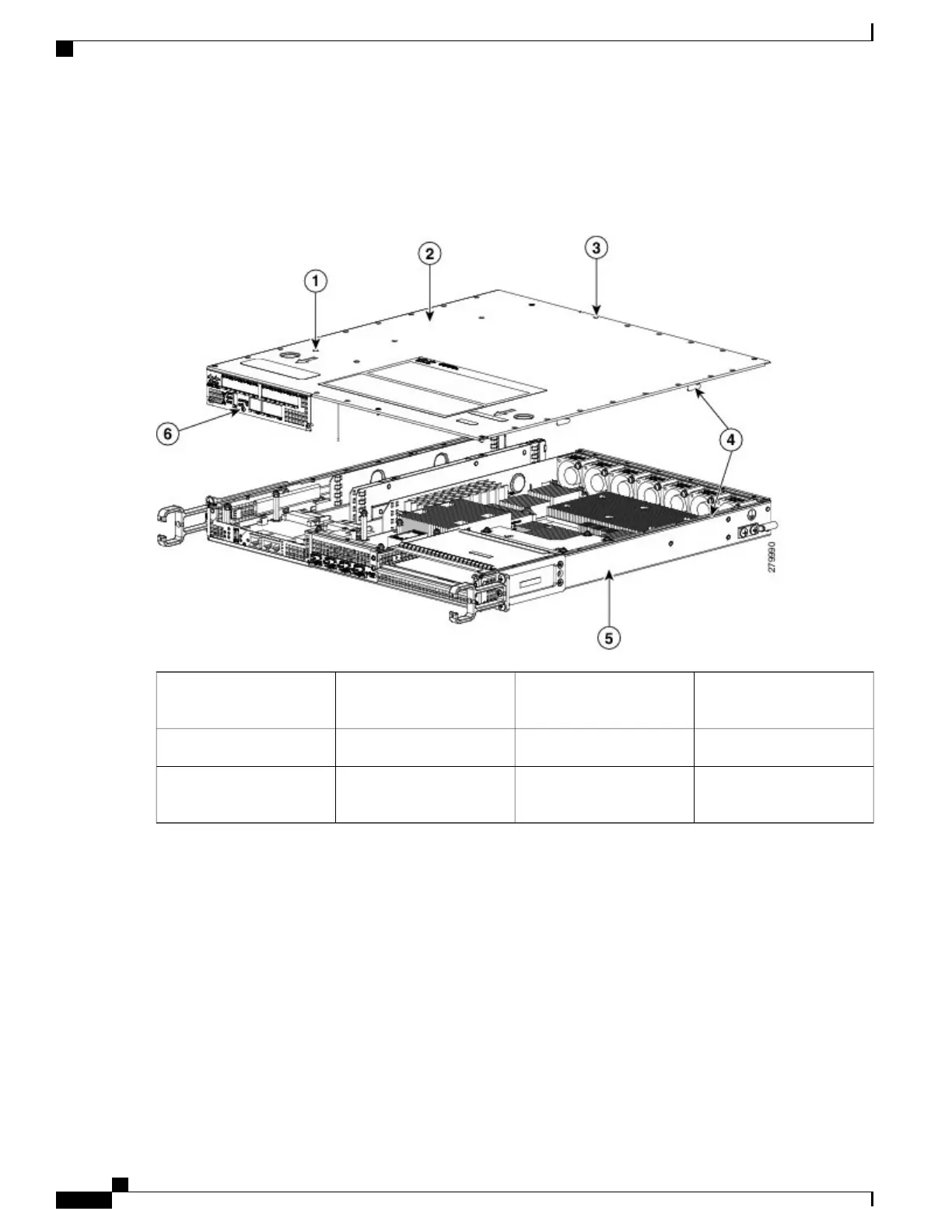
b) Loosen the three screws on the faceplate at the front of the chassis, as shown in the following figure, callout 6.
Figure 247: Removing the Cisco ASR 1001 Router Cover
Interlock hook feature on
the chassis cover and base
4Interlock pin safety feature1
Chassis base5Chassis cover2
Three screws at the front of
the chassis faceplate
6Top surface perimeter
screws
3
c) Using both hands, gently slide the cover forward and off of the chassis.
The cover will not come off the chassis if the power supplies are present in the chassis.Note
Cisco ASR 1000 Series Router Hardware Installation Guide
510
Removing and Replacing FRUs from the Cisco ASR 1000 Series Routers
Removing and Replacing the Cisco ASR 1001 Router DIMM Memory Modules

Table of Contents

Other manuals for Cisco ASR 1002-X

Questions and Answers:

Question and Answer IconNeed help?

Do you have a question about the Cisco ASR 1002-X and is the answer not in the manual?

Cisco ASR 1002-X Specifications

General IconGeneral
Form FactorRack-mountable
Rack Units2RU
Integrated ServicesYes
Maximum Memory16 GB
Built-in Gigabit Ethernet Ports6
Input Voltage100-240 VAC
Operating Temperature32 to 104°F (0 to 40°C)
RedundancyPower supply redundancy
Network Interface ModulesUp to 4 SPA/SIP slots
Embedded Services Processor (ESP)ESP-20
Maximum Packet per Second (PPS)15 Mpps
Height3.5 inches
Fixed Ports6 GE ports
Memory4 GB (default), 16 GB (maximum)
Power SupplyDual power supplies (AC or DC)
Dimensions (H x W x D)3.5 x 17.5 x 19.0 in (8.9 x 44.5 x 48.3 cm)

Related product manuals