EasyManuals Logo

Cisco ASR 1002-X Hardware Installation Guide

Cisco ASR 1002-X
702 pages
To Next Page IconTo Next Page
To Previous Page IconTo Previous Page
Page #583 background imageLoading...
Page #583 background image
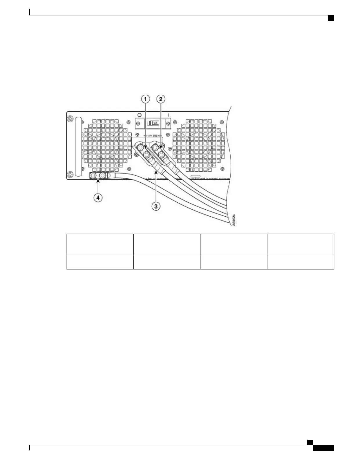
The following figure shows the DC power supply terminal block with cables connected for the ASR1006-PWR-DC
power supply of the Cisco ASR 1006 Router.
Figure 269: Cisco ASR 1006 Router DC Power Supply Terminal Block Cable Connections
Protective sleeving around
the stud and cable
3Negative lead1
Ground stud and cable4Positive lead2
Cisco ASR 1000 Series Router Hardware Installation Guide
549
Removing and Replacing FRUs from the Cisco ASR 1000 Series Routers
Removing and Replacing a DC Power Supply in Cisco ASR 1006 Router

Table of Contents

Other manuals for Cisco ASR 1002-X

Questions and Answers:

Question and Answer IconNeed help?

Do you have a question about the Cisco ASR 1002-X and is the answer not in the manual?

Cisco ASR 1002-X Specifications

General IconGeneral
Form FactorRack-mountable
Rack Units2RU
Integrated ServicesYes
Maximum Memory16 GB
Built-in Gigabit Ethernet Ports6
Input Voltage100-240 VAC
Operating Temperature32 to 104°F (0 to 40°C)
RedundancyPower supply redundancy
Network Interface ModulesUp to 4 SPA/SIP slots
Embedded Services Processor (ESP)ESP-20
Maximum Packet per Second (PPS)15 Mpps
Height3.5 inches
Fixed Ports6 GE ports
Memory4 GB (default), 16 GB (maximum)
Power SupplyDual power supplies (AC or DC)
Dimensions (H x W x D)3.5 x 17.5 x 19.0 in (8.9 x 44.5 x 48.3 cm)

Related product manuals