The following figure shows the terminal block ground lugs for the ASR1013/06-PWR-DC power supply of the Cisco
ASR 1006 Router.
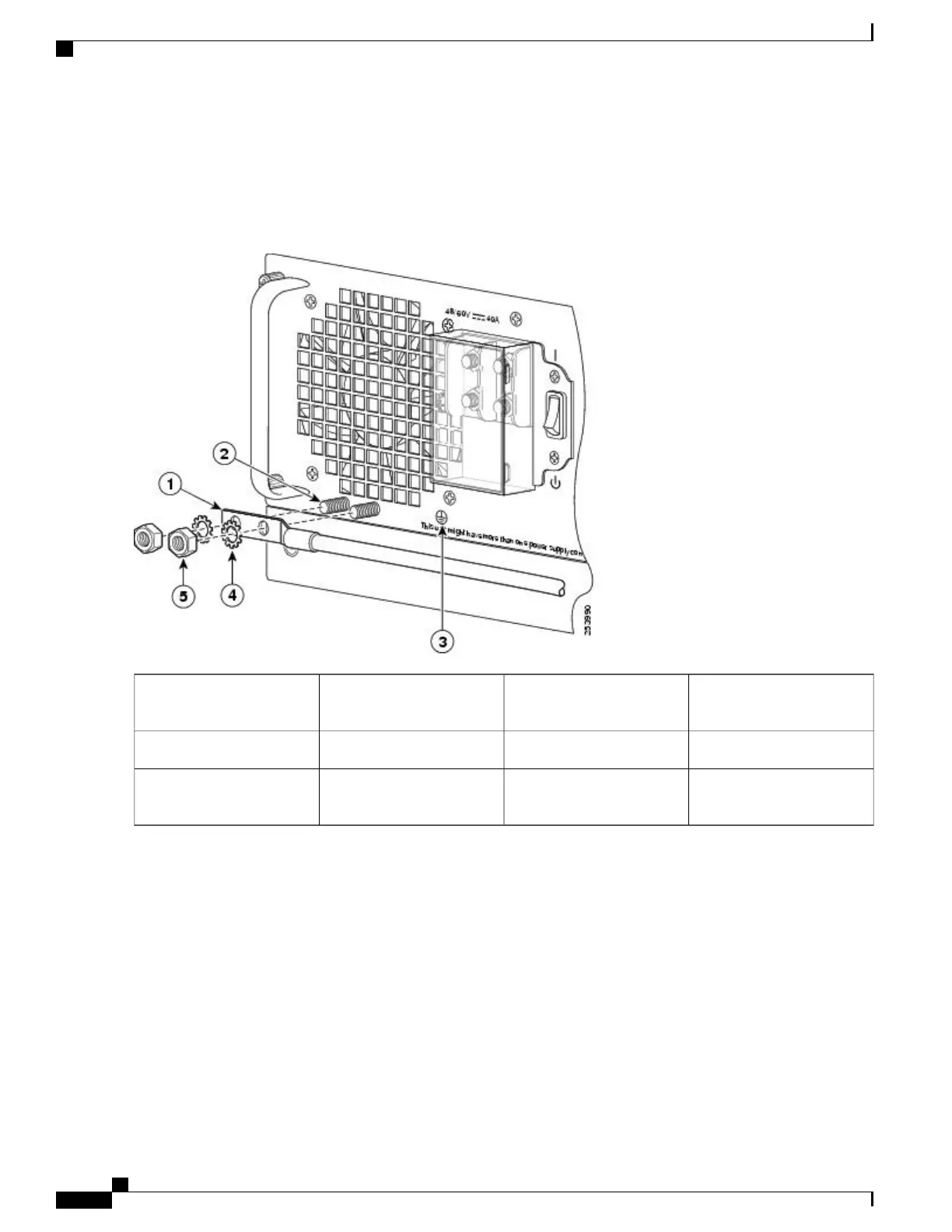
Figure 272: Cisco ASR 1006 Router DC Power Supply (ASR1013/06-PWR-DC) Ground Lug Installation
Flat washer4DC power supply grounding
stud with wire
1
Kepnut screw5Grounding screws2
——
DC power supply ground
symbol
3
Step 8
For easier cable-management, insert the positive cable first. Replace the ground lug with cable in the following order:
a) Flat Washer
b) Ground lug with positive wire
c) Kepnut screw
Step 9
Tighten the Kepnut screw (use the screwdriver to tighten the ground screw in the terminal block to a torque of 20+/–2
in-lbs / 2 per.) and repeat the same steps for the negative wires.
Secure the wires coming in from the terminal block so that they cannot be disturbed by casual contact.Note
Step 10
Use tie wraps to secure the wires, so that the wires are not pulled from the terminal block by casual contact. Ti-wrap
studs are located below the power supply terminal block.
The ground wire must contain a loop when securing it to the tie-wrap tab to prevent it from being pulled
out.
Note
Cisco ASR 1000 Series Router Hardware Installation Guide
554
Removing and Replacing FRUs from the Cisco ASR 1000 Series Routers
Removing and Replacing a DC Power Supply in Cisco ASR 1006 Router
 Loading...


