EasyManuals Logo

Cisco ASR 1002-X Hardware Installation Guide

Cisco ASR 1002-X
702 pages
To Next Page IconTo Next Page
To Previous Page IconTo Previous Page
Page #622 background imageLoading...
Page #622 background image
DETAILED STEPS
Step 1
Slip on the ESD-preventive wrist strap that was included in the accessory kit.
Step 2
Before you turn off a power supply, make certain the chassis is grounded.
Step 3
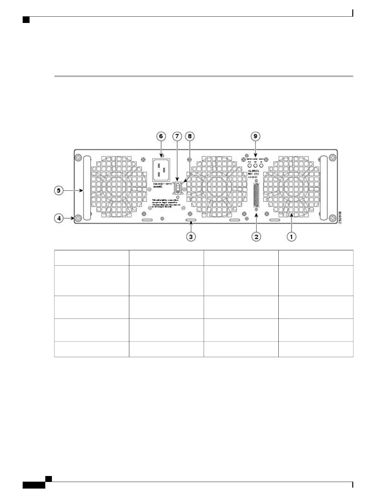
Turn the power supply standby switch to the Standby position. See the following figure.
Figure 293: Cisco ASR 1013 Router AC Power Inlet and Standby Switch
AC power inlet6AC power supply fan1
AC power supply standby
switch. A standby switch is
not considered a disconnect.
7DB-25 alarm connector*2
Protective sides around the
standby switch
8Cable tie wrap tabs3
AC power supply LEDs9AC power supply captive
screws
4
AC power supply handle5
Cisco ASR 1000 Series Router Hardware Installation Guide
588
Removing and Replacing FRUs from the Cisco ASR 1000 Series Routers
Removing and Replacing an AC Power Supply in Cisco ASR 1013 Router

Table of Contents

Other manuals for Cisco ASR 1002-X

Questions and Answers:

Question and Answer IconNeed help?

Do you have a question about the Cisco ASR 1002-X and is the answer not in the manual?

Cisco ASR 1002-X Specifications

General IconGeneral
Form FactorRack-mountable
Rack Units2RU
Integrated ServicesYes
Maximum Memory16 GB
Built-in Gigabit Ethernet Ports6
Input Voltage100-240 VAC
Operating Temperature32 to 104°F (0 to 40°C)
RedundancyPower supply redundancy
Network Interface ModulesUp to 4 SPA/SIP slots
Embedded Services Processor (ESP)ESP-20
Maximum Packet per Second (PPS)15 Mpps
Height3.5 inches
Fixed Ports6 GE ports
Memory4 GB (default), 16 GB (maximum)
Power SupplyDual power supplies (AC or DC)
Dimensions (H x W x D)3.5 x 17.5 x 19.0 in (8.9 x 44.5 x 48.3 cm)

Related product manuals