EasyManuals Logo

Cisco ASR 1002-X Hardware Installation Guide

Cisco ASR 1002-X
702 pages
To Next Page IconTo Next Page
To Previous Page IconTo Previous Page
Page #635 background imageLoading...
Page #635 background image
DETAILED STEPS
Step 1
There are two power supplies installed. At the rear of the chassis, check whether the power switch on the chassis is in
the Standby position.
Do not install the Cisco ASR 1001 Router power supplies without the top cover on the Cisco ASR 1001
chassis.
Warning
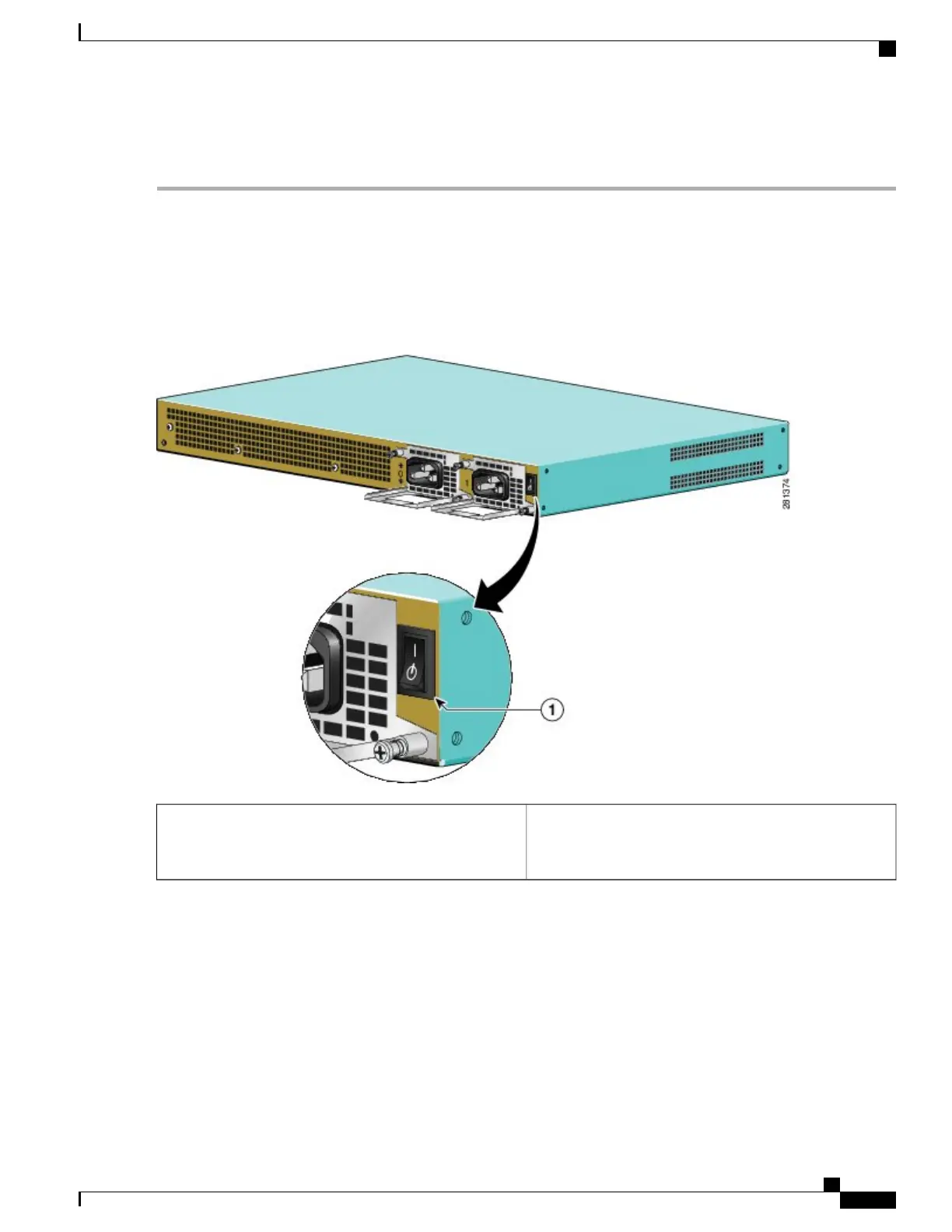
The following figure shows the Cisco ASR 1001 Router AC power supply standby switch.
Figure 301: Cisco ASR 1001 Router AC Power Supply Standby Switch
Cisco ASR 1001 Router AC power supply Standby switch.
This switch does not disconnect power from the power
source.
1
Cisco ASR 1000 Series Router Hardware Installation Guide
601
Removing and Replacing FRUs from the Cisco ASR 1000 Series Routers
Installing the AC Power Supply into Cisco ASR 1001 Router

Table of Contents

Other manuals for Cisco ASR 1002-X

Questions and Answers:

Question and Answer IconNeed help?

Do you have a question about the Cisco ASR 1002-X and is the answer not in the manual?

Cisco ASR 1002-X Specifications

General IconGeneral
Form FactorRack-mountable
Rack Units2RU
Integrated ServicesYes
Maximum Memory16 GB
Built-in Gigabit Ethernet Ports6
Input Voltage100-240 VAC
Operating Temperature32 to 104°F (0 to 40°C)
RedundancyPower supply redundancy
Network Interface ModulesUp to 4 SPA/SIP slots
Embedded Services Processor (ESP)ESP-20
Maximum Packet per Second (PPS)15 Mpps
Height3.5 inches
Fixed Ports6 GE ports
Memory4 GB (default), 16 GB (maximum)
Power SupplyDual power supplies (AC or DC)
Dimensions (H x W x D)3.5 x 17.5 x 19.0 in (8.9 x 44.5 x 48.3 cm)

Related product manuals