CDM-625A Advanced Satellite Modem MN-CDM625A
Appendix M Revision 4
M–27
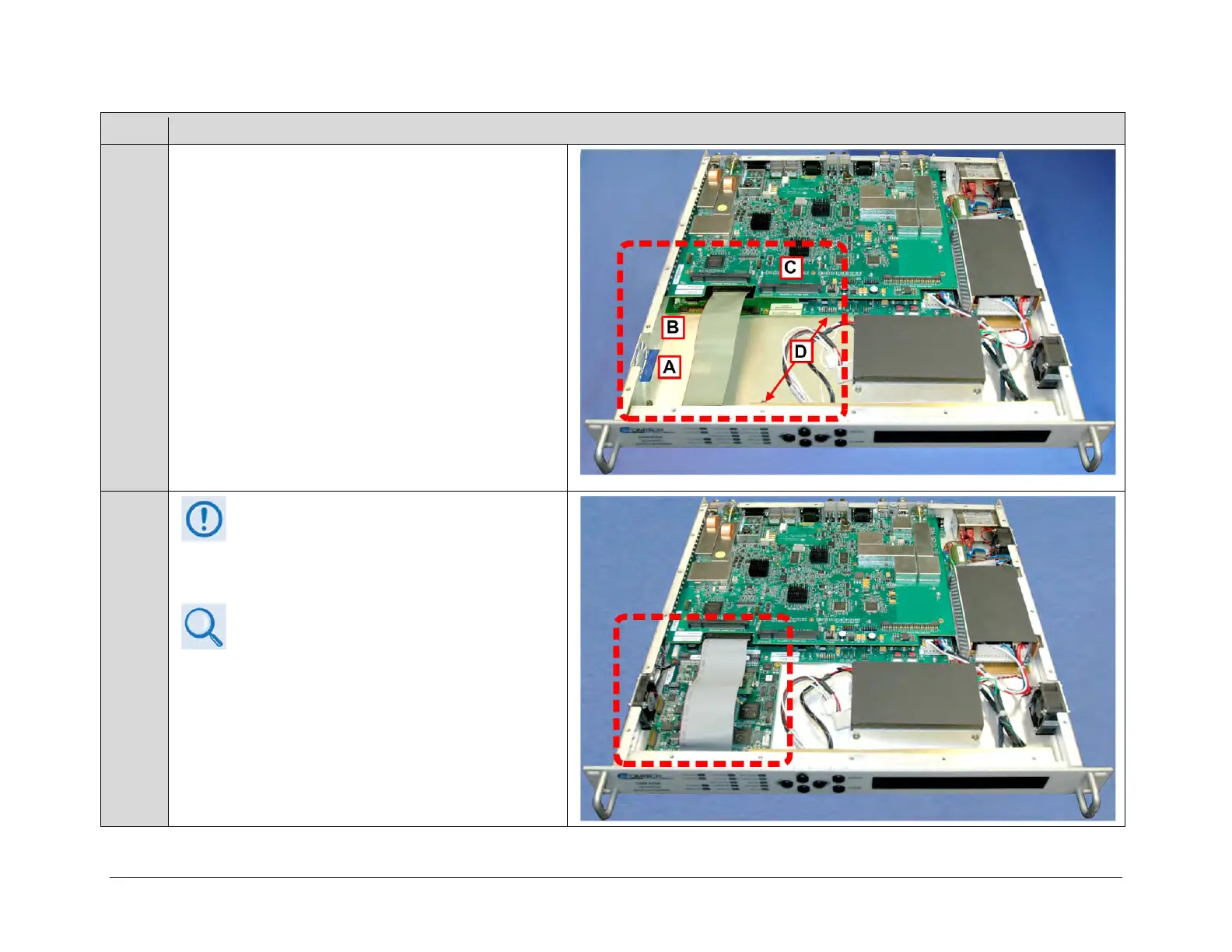
The illustration at right identifies the upgrade locations
within the chassis for:
• (A) Installation of the fan into the chassis;
• (B) Plug-in of the fan power cable into the
CDM-625A’s framing board;
• (C) Assembly of the VersaFEC-2 Option Card onto
the CDM-625A’s modem board;
• (D) Assembly of the Air Baffle to the chassis floor.
If the optional IP Packet Processor Kit (CEFD
P/N KT-0000176) has already been installed
into the CDM-625A Chassis, then it is not
necessary to install the kit fan assembly and
Appendix L. IP PACKET PROCESSOR
OPTION (Sect. L.5 IP Packet Processor Field
You may proceed to Step 6 to continue with the field
upgrade procedure..