Menu 10
Parameter
structure
Keypad and
display
Parameter
x.00
Parameter
description format
Advanced parameter
descriptions
Macros
Serial comms
protocol
Electronic
nameplate
Performance
Feature look-
up table
164 Unidrive SP Advanced User Guide
www.controltechniques.com Issue Number: 7
C.Full SMARTCARD trip: SMARTCARD full
184 Delete a data block or use different SMARTCARD
CL2 Analog input 2 current loss (current mode)
28 Check analog input 2 (terminal 7) current signal is present (0-20mA, 4-20mA etc.)
CL3 Analog input 3 current loss (current mode)
29 Check analog input 3 (terminal 8) current signal is present (0-20mA, 4-20mA etc.)
CL.bit Trip initiated from the control word (Pr 6.42)
35 Disable the control word by setting Pr 6.43 to 0 or check setting of Pr 6.42
C.Optn SMARTCARD trip: Solutions Modules fitted are different between source drive and destination drive
180
Ensure correct Solutions Modules are fitted
Ensure Solutions Modules are in the same Solutions Module slot
Press the red reset button
C.rdo SMARTCARD trip: SMARTCARD has the Read Only bit set
181
Enter 9777 in Pr xx.00 to allow SMARTCARD Read / Write access
Ensure card is not writing to data locations 500 to 999
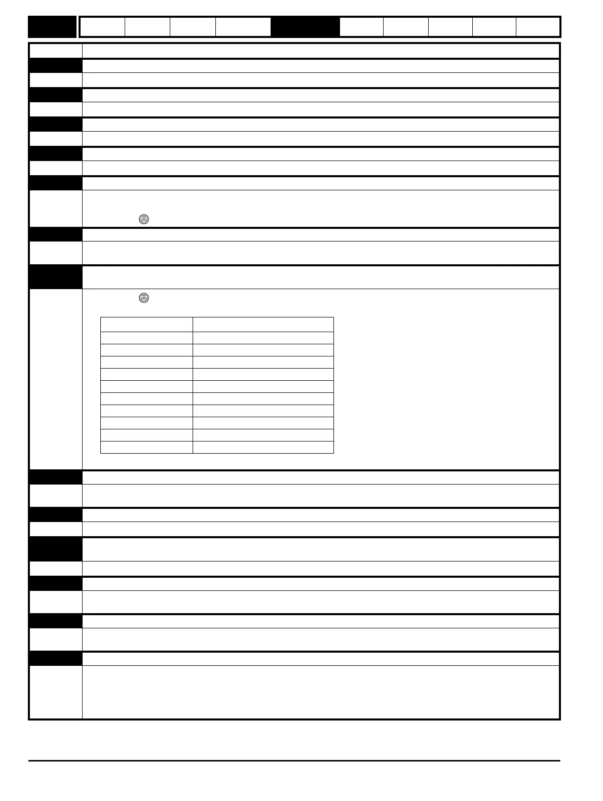
C.rtg
SMARTCARD trip: SMARTCARD attempting to change the destination drive ratings
No drive rating parameters have been transferred
186
Press the red reset button
Drive rating parameters are:
The above parameters will be set to their default values.
C.Typ SMARTCARD trip: SMARTCARD parameter set not compatible with drive
187
Press the reset button
Ensure destination drive type is the same as the source parameter file drive type
dESt Two or more parameters are writing to the same destination parameter
199 Set Pr xx.00 = 12001 check all visible parameters in the menus for duplication
EEF
EEPROM data corrupted - Drive mode becomes open loop and serial comms will timeout with remote keypad on the drive
RS485 comms port.
31 This trip can only be cleared by loading default parameters and saving parameters
EEF1 EEPROM data corrupted
36
Indicates the power was removed when parameters were being saved.
The drive will revert back to the parameters set that was last saved successfully.
Enc1 Drive encoder trip: Encoder power supply overload
189
Check encoder power supply wiring and encoder current requirement
Maximum current = 200mA @ 15V, or 300mA @ 8V and 5V
Enc2 Drive encoder trip: Wire break
190
Check cable continuity
Check wiring of feedback signals is correct
Check encoder power is set correctly
Replace feedback device
If wire break detection on the main drive encoder input is not required, set Pr 3.40 = 0 to disable the Enc2 trip
Trip Diagnosis
Parameter Function
2.08 Standard ramp voltage
4.05/6/7, 21.27/8/9 Current limits
5.07, 21.07 Motor rated current
5.09, 21.09 Motor rated voltage
5.17, 21.12 Stator resistance
5.18 Switching frequency
5.23, 21.13 Voltage offset
5.24, 21.14 Transient inductance
5.25, 21.24 Stator inductance
6.06 DC injection braking current
http://nicontrols.com