Parameter
structure
Keypad and
display
Parameter
x.00
Parameter
description format
Advanced parameter
descriptions
Macros
Serial comms
protocol
Electronic
nameplate
Performance
Feature look-
up table
Menus 15 to 17
SM-Uni Enc Pl
Unidrive SP Advanced User Guide 243
Issue Number: 7 www.controltechniques.com
All the returned values have been offset by 32,768 which is the most significant bit. The last byte has an addition offset of 16,384 to denote that it is
the last byte.
First check the CRC (which is also checked by the Solutions Module), this is the XOR of all the data bytes before bit position by bit position, for
example the least significant bit of the CRC is zero as the XOR(001111) is zero.
Words 3 to 6 are the position with the least significant bit as the least significant bit of word 6 so any unused bits being placed in the more significant
part of word 3. Below are the numbers laid out in the correct order:
Shifted to turns and position (which is 12 bits then 14 bits):
1101 0110 0101 (end of turns and start of the position) 10 0011 1001 0111
3429 9111
So the absolute position is 3429/9111 which should be compared to the displayed interpolated position of 3429/9112.
SC.EnDat
The Heidenhain EnDat protocol is a synchronous protocol using the following message format.
The following commands are supported:
The following is an example of the response when the encoder to send position command is used.
The example shown above is for an encoder with 12 bits representing the turns and 13 bits representing the position within a turn. The position
command only requires one byte to be sent to the encoder. Bits 14 and 13 can both be set in the transmit register to indicate that this is both the first
and last byte of the message.
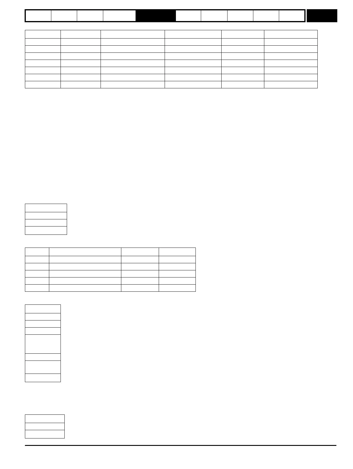
If any other command is used then the response is as follows:
Word number Returned value Returned value in hex. Data in decimal Data in hex. Data in binary
1 32,832 0x8040 64 0x40 0100 0000
2 32,834 0x8042 66 0x42 0100 0010
3 32,771 0x8003 03 0x03 0000 0011
4 32,857 0x8059 89 0x59 0101 1001
5 32,867 0x8063 99 0x63 0110 0011
6 32,919 0x8097 151 0x97 1001 0111
7 49,324 0xc0ac 172 0xac 1010 1100
Word 3 Word 4 Word 5 Word 6
3 89 99 151
0000 0011 0101 1001 0110 0011 1001 0111
Command
1
st
byte
Address
Data (LSB)
Data (MSB)
4
th
byte
Code Command Address Data
0x00 Encoder to send position Don’t care Don’t care
0x01 Selection of memory area MRS code Don’t care
0x03 Encoder to receive parameter Address Data
0x04 Encoder to send parameter Address Don’t care
0x05 Encoder to receive reset Don’t care Don’t care
LS byte
1
st
byte
Bit 7-0 = 0
Bit 7-0 = 0
Bit 7-0 = 0
Bit 7-0 = 0
Bits 5-0 = 0
Bit 6 = Alarm bit
Bit 7 = Bit 0 of position
Bits 7-0 = Bits 8-1 of position
Bits 3-0 = Bits 12-9 of position
Bits 7-4 = Bits 3-0 of turns
MS byte
8
th
byte
Bits 7-0 = Bits 11-4 of turns
Address
1
st
byte
Data (LSB)
Data (MSB)
3
rd
byte
http://nicontrols.com