Chapter 11 Motion Control Instructions
11-175
CombineMode is set to 1
=
= Position variation of Master axis1 ×
GearRatioNumeratorM1
GearRatioDenominatorM1
−
Position Variation of Master axis2 ×
GearRatioNumeratorM2
GearRatioDenominatorM2
The master gear ratio numerator and denominator are the factors to adjust the position variations
of two master axes. See the formula above.
MasterValueSource can be set to 0 (command position) and 1 (actual position) so as to specify the
source of the position variation. If the value is set to 0, add up the master axis command position
variations. If the value is set to 1, subtract one master axis actual position variation from another
master axis actual position variation.
The Acc, Dec and Jerk indicate that the master axis has been in motion before the instruction is
executed. If the instruction is executed at the moment, the slave axis will speed up or down
according to the set acceleration, deceleration and jerk so as to realize the synchronization with the
master position variations. When the synchronization is achieved, InSync is TRUE and the
instruction execution is completed.
Use other motion instruction (such as MC_Stop instruction) for the control over the slave axis so as
to end the master-slave axis relationship in the instruction. Set the value of BufferMode of other
motion instruction which has the Buffermode parameter to 0 in order to abort the
MC_CombineAxes instruction and disconnect the master-slave axis relationship.
If the master axis gear ratio is to be switched during the motion, use another MC_CombineAxes
instruction to abort the MC_CombineAxes instruction which is being executed.
Programming Example
The example of executing the MC_CombineAxes instruction is described as below.
1. The variable table and program
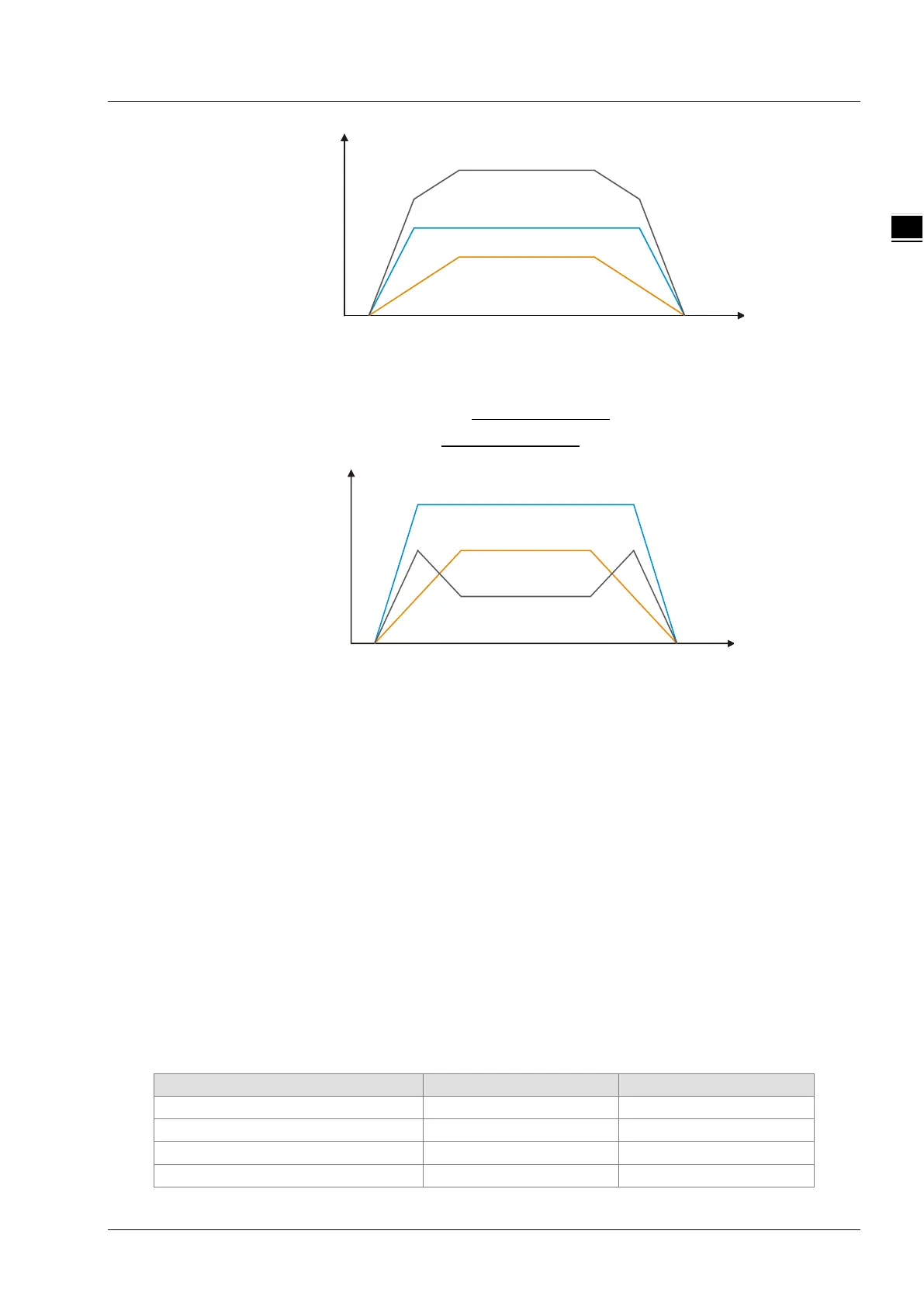
Slave axis
Master a xis 1
Master a xis 2
Velocity
Time
Master a xis 1
Master a xis 2
Slave axis
Velocity
Time

 Loading...


