DVP-15MC Series Motion Controller Operation Manual
3-4
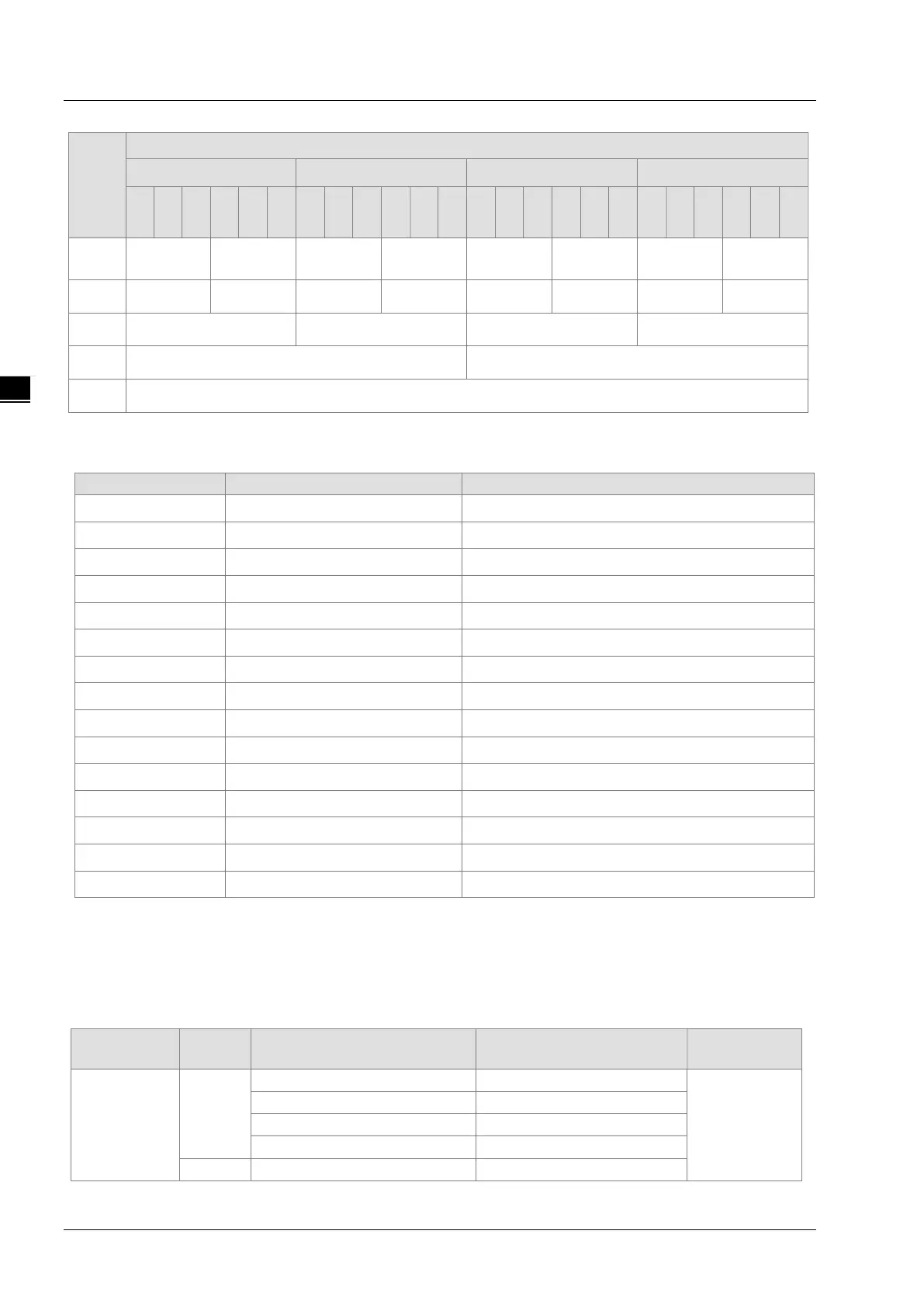
name
Corresponding relationships
The 5
th
WORD The 6
th
WORD The 7
th
WORD The 8
th
WORD
Bit
0
...
Bit
7
Bit
8
…
Bit
15
Bit
0
...
Bit
7
Bit
8
…
Bit
15
Bit
0
...
Bit
7
Bit
8
…
Bit
15
Bit
0
...
Bit
7
Bit
8
…
Bit
15
%MX
7
7
10.7
1.7
12.7
13.7
14.7
15.7
%MB %MB8 %MB9 %MB10 %MB11 %MB12 %MB13 %MB14 %MB15
%MW %MW4 %MW5 %MW6 %MW7
%MD %MD2 %MD3
%ML %ML1
3.1.2.2 Valid Ranges of Devices
The table of valid ranges of the devices in DVP-15MC series motion controller
%IX %IX0.0~%IX0.7 %IX0.0~%IX127.7
%QX %QX0.0~%QX0.7 %QX0.0~%QX127.7
%MX %MX0.0 %MX0.0~%MX131071.7
%IB %IB0 %IB0~%IB127
%QB %QB0 %QB0~%QB127
%MB %MB0 %MB0~%MB131071
%IW %IW0 %IW0~%IW63
%QW %QW0 %QW0~%QW63
%MW %MW0 %MW0~%MW65535
%ID %ID0 %ID0~%ID31
%QD %QD0 %QD0~%QD31
%MD %MD0 %MD0~%MD32767
%IL %IL0 %IL0~%IL15
%QL %QL0 %QL0~%QL15
%ML %ML0 %ML0~%ML16383
The table of Modbus device addresses
The Modbus addresses which are within the range of 16#0000~16#FFFF can be accessed via the standard
MODBUS function code 01, 02, 03, 05, 06, 16#0F and 16#10. When a MODBUS function code is used to
access bit devices, please access QX and IX bit devices. If MX bit devices need be accessed, the MW device
is accessed and then the values in the MX bit devices can be got through the MW device.
See Section 3.1.2.1 for details on the correponding relationship between MW and MX devices.
Device area
Range Modbus address
I
(Input)
Bit
Standard
Modbus
address

 Loading...


