DVP-15MC Series Motion Controller Operation Manual
A-2
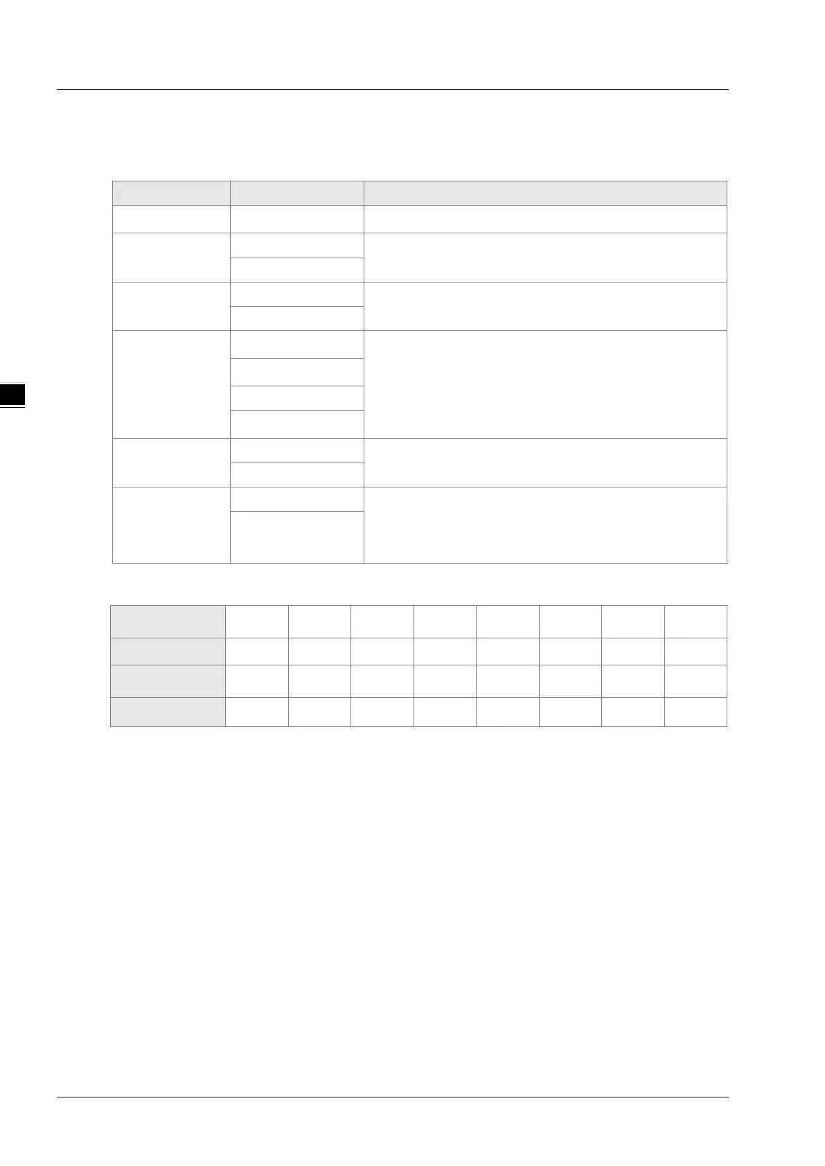
A.1 Message Format in ASCII Mode
Communication data structure
Field name Components Explanation
Start character
STX
Start character “:”, the corresponding ASCII code: 16#3A
Communication
address
ADR 1
Communication address consists of two ASCII codes.
ADR 0
Function code
CMD 1
Function code consists of two ASCII codes.
CMD 0
Data
DATA (0)
Data content consists of 2n ASCII codes, n≤205.
DATA (1)
……….
DATA (n-1)
LRC Check
LRC CHK 1
LRC check consists of two ASCII codes.
LRC CHK 0
End character
END1
End character consists of two ASCII codes.
END1 = CR (16#0D),
END0 = LF (16#0A)
END0
The corresponding relation between hexadecimal character and ASCII code:
“0” “1” “2” “3” “4” “5” “6” “7”
ASCII code 16#30 16#31 16#32 16#33 16#34 16#35 16#36 16#37
“8” “9” “A” “B” “C” “D” “E” “F”
ASCII code 16#38 16#39 16#41 16#42 16#43 16#44 16#45 16#46
ADR (Communication address)
The valid range of communication address: 0~254.
Communication address: 0 means the broadcast message is sent to all slaves and the slaves which
have received the message will not make any response. If communication address is not 0, slaves
will respond to master after receiving the message normally. For instance, ASCII codes for the
communication address of 16 are denoted below.
Decimal 16 is equal to hexadecimal 10. (ADR 1, ADR 0) =‘10’, ‘1’=31H, ‘0’ = 30H
Function code and data
The data format is determined by function codes. For example, to read the two continuous address
data with hexadecimal 16#0000 as the start address in DVP-15MC series motion controller. The
communication address of DVP-15MC series motion controller is 1, 16#0000 is the Modbus address
of %MW0 in the controller.
The data explanation is shown as below:
PC→DVP-15MC series motion controller
3A 30 31 30 33 30 30 30 30 30 30 30 32 46 41 0D 0A
DVP-15MC series motion controller→PC
3A 30 31 30 33 30 34 30 30 30 31 30 30 30 32 46 35 0D 0A

 Loading...


