Chapter 8 Logic Instructions
8-9
Explanation of Logic Instructions
If the used instruction has EN and ENO input parameters and the value of EN is FALSE (0), the function of
the instruction will not be performed and the output of the instruction will not be updated. However, if the
value of EN of the instruction is TRUE (1), the function of the instruction will be performed and the output will
be updated.
The output state of ENO is consistent with that of EN. When EN is TRUE, ENO changes to TRUE. When EN
is FALSE, ENO changes to FALSE.
When the instruction is a function block (FB) and its EN changes from TRUE to FALSE after the FB
instruction is executed, the execution of the FB instruction will continue, but the output values of the FB
instruction will not be updated.
Sequence Input /Output Instructions
FB/FC
Explanation Applicable model
FB
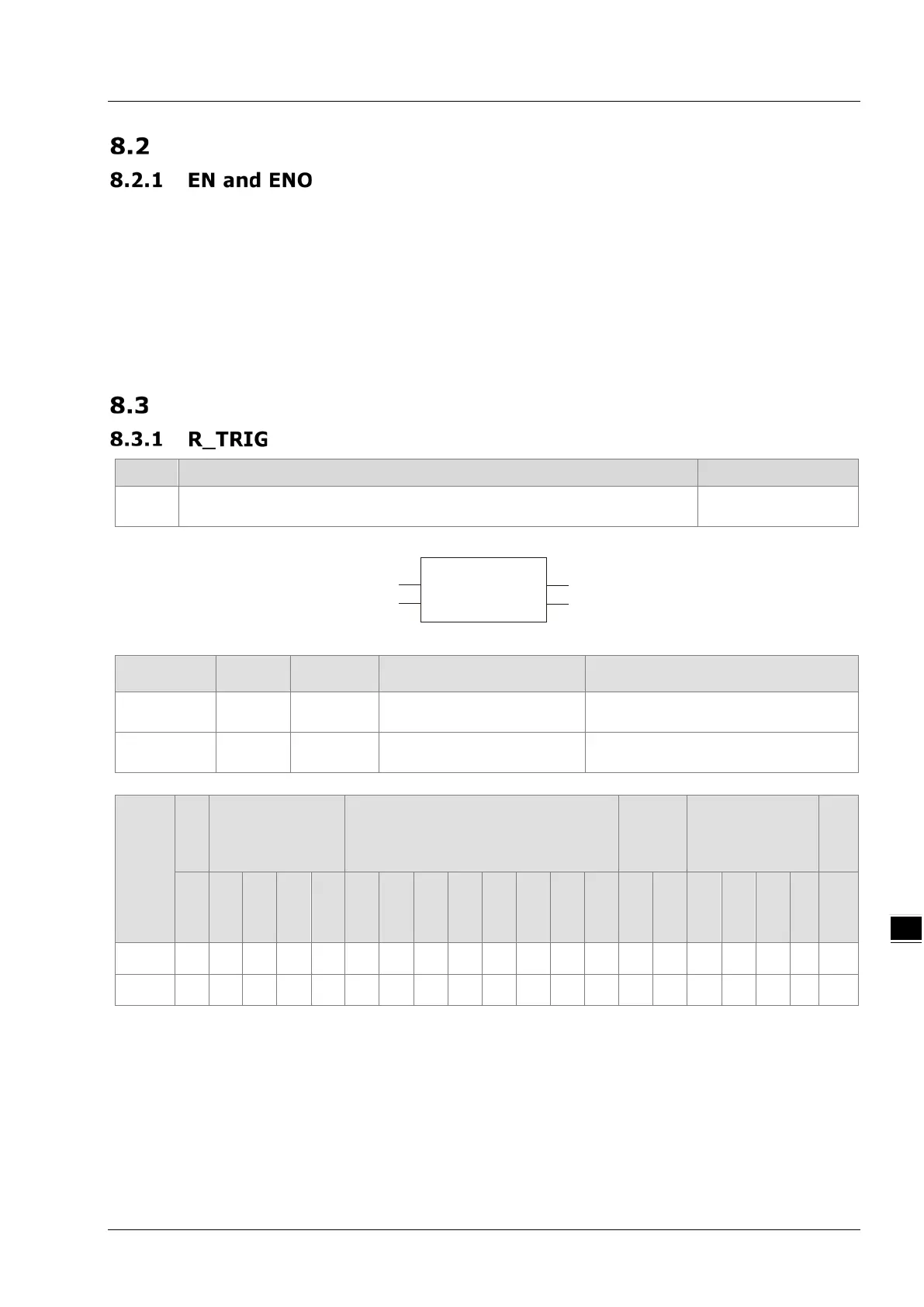
R_TRIG is used for the rising edge trigger.
Parameters
Meaning
Description Valid range
CLK
Input Rising edge trigger signal TRUE or FALSE
Q
Output
Output Output for a period TRUE or FALSE
Boolean
Bit string Integer
Real
number
Time, date
String
BOOL
BYTE
UINT
SINT
INT
DINT
REAL
STRING
CLK
●
Q
●
Note:
The symbol ● indicates that the parameter is allowed to connect to the variable or constant of the data
type.
Function Explanation
When CLK of R_TRIG changes from FALSE to TRUE, Q output is TRUE for only one period. In other
circumstances, Q is FALSE.
Precautions for Correct Use
Q will have no output until the rising edge signal at CLK is detected.
R_TRIG
EN ENO
CLK
Q
R_TRIG_instance

 Loading...


