Appendix A. Modbus Communication
A-15
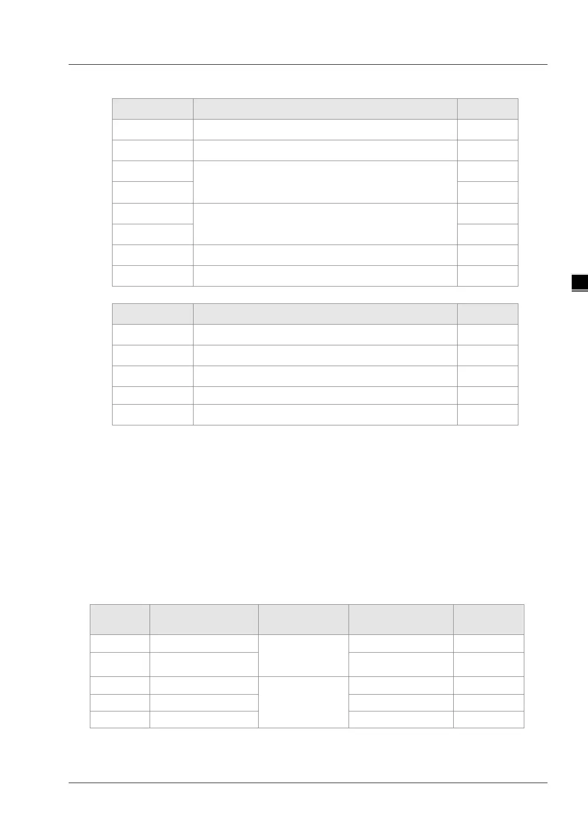
Data structure of a response message:
Byte NO. Name Byte
Byte0
Modbus ID
Single byte
Byte1
Function code
Single byte
Byte2
The start address of bit registers where to write values
High byte
Byte3 Low byte
Byte4
The number of bit registers where to write values
High byte
Byte5 Low byte
Byte6
Low byte of CRC check sum
Low byte
Byte7
High byte of CRC check sum
High byte
Data structure of an exception response message:
Byte NO. Name Byte
Byte0 Modbus ID Single byte
Byte1 16#80+ Function code Single byte
Byte2 Exception response code
High byte
Byte3
Low byte of CRC check sum
Low byte
Byte4
High byte of CRC check sum
High byte
Note: How many bytes of data in the request message depend on the number of bit registers in
the request message.
Example
The value of %QX0.0~%QX0.7 is set to 1000 0001 and the address of %QX0.0 is 16#A000 via
function code 0F in DVP-15MC series motion controller.
Request message: 01 0F A0 00 00 08 01 81 26 55
Response message: 01 0F A0 00 00 08 76 0D
A.6 Table of Registers and Corresponding Modbus
addresses
Register numbers in the motion control module of DVP-15MC series and corresponding addresses
are listed below:
Register
name
Register number Explanation Address (hex) Attribute
I %IX0.0~%IX127.7
Bit registers
6000 ~ 63FF
Read only
Q %QX0.0~%QX127.7 A000 ~ A3FF
Read/write
I %IW0~%IW63
Word registers
8000 ~ 803F
Read only
Q %QW0~%QW63 A000 ~ A03F
Read/write
M %MW0~%MW32767 0000 ~ 7FFF Read/write

 Loading...


