DVP-15MC Series Motion Controller Operation Manual
A-14
Byte7
High byte of CRC check sum
High byte
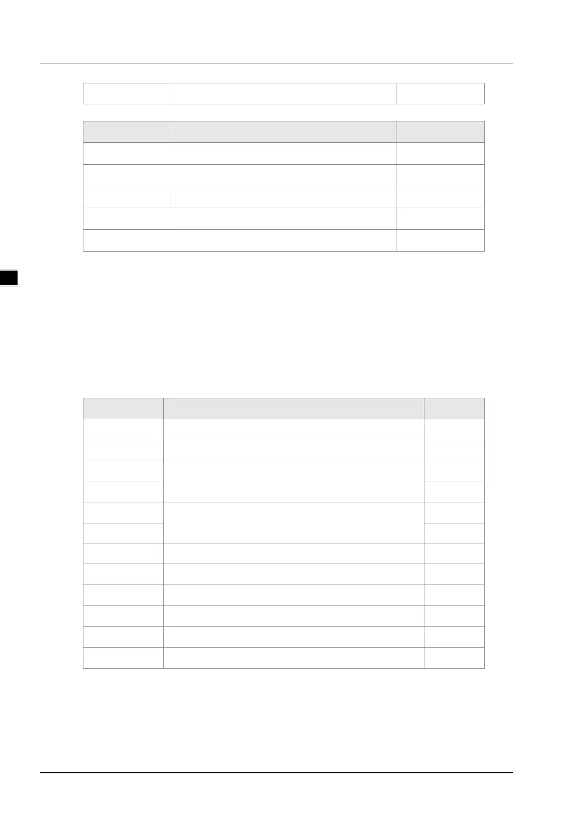
Data structure of an exception response message:
Byte NO. Name Byte
Byte0 Modbus ID Single byte
Byte1 16#80+ Function code Single byte
Byte2 Exception response code Single byte
Byte3
Low byte of CRC check sum
Low byte
Byte4
High byte of CRC check sum
High byte
Note: The written value 16#0000 for the bit register in request message or response message
indicates the value FALSE is written in the bit register; the written value 16#FF00 for the bit
register indicates the value TRUE is written in the bit register.
Example
The value of %QX0.0 in DVP-15MC series motion controller is set to TRUE and the address of
%QX0.0 is set to 16#A000 via function code 05.
Request message: 01 05 A0 00 FF 00 AE 3A
Response message: 01 05 A0 00 FF 00 AE 3A
Function code 16#0F writes multiple bit register values
Data structure of a request message:
Byte NO. Name Byte
Byte0
Modbus ID
Single byte
Byte1
Function code
Single byte
Byte2
The start address of the bit registers where to write
values
High byte
Byte3 Low byte
Byte4
The number of bit registers where to write values
High byte
Byte5 Low byte
Byte6 The number of bytes of bit registers where to write values
Single byte
Byte7 The value written to the bit register Single byte
… The value written to the bit register Single byte
Byte n The value written to the bit register Single byte
Byte n+1
Low byte of CRC check sum
Low byte
Byte n+2
High byte of CRC check sum
High byte

 Loading...


