TC Description
Doc. 065031-04 1/08 95
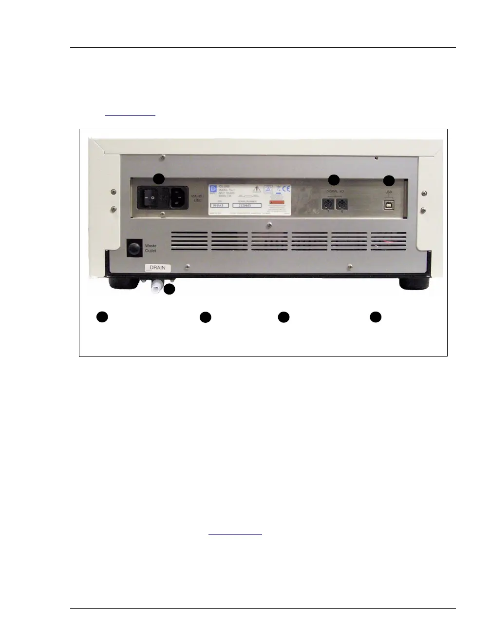
2.21 TC Rear Panel
Figure 2-53 illustrates the rear panel of the TC.
Main Power Switch, Fuse Holder, and Power Receptacle
The rear panel power switch is the main power switch for the TC. Turn on the
main power switch before initial operation, and leave the switch on unless
instructed to turn it off (for example, before performing a service procedure).
NOTE For routine on/off control of the TC, use the POWER
button on the front of the module. To turn off the TC,
press and hold the
POWER button for 2 seconds.
The fuse holder contains two 2-amp fuses (P/N 954776). For instructions on how
to change the fuses, see Section 9.29
.
The power cord plugs into the IEC 320 three-prong receptacle.
Figure 2-53. TC Rear Panel
USB Receptacle
(“B” Connector)
1
2
3
4
2
3
4
Main Power Switch,
Fuse Holder, and
Power Receptacle
1
Digital I/O
Connectors (2)
Drain Port