2 • DC Description
Doc. 065031-04 1/08 79
2.18 I/O Option
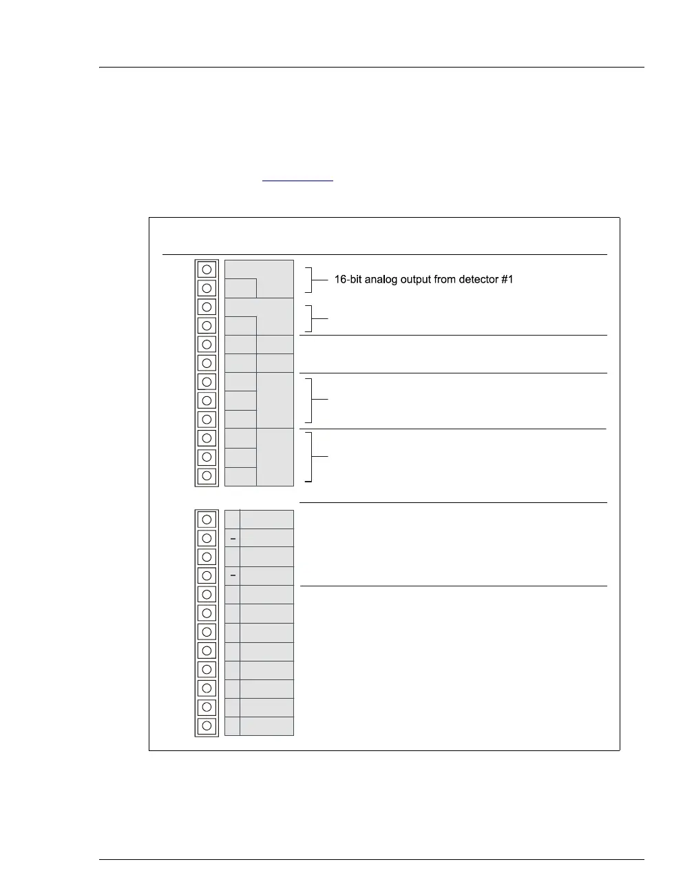
When the I/O option (P/N 062201) is installed, two 12-pin connector strips are on
the DC rear panel. Figure 2-44
describes the functions assigned to each connector
pin.
Figure 2-44. Optional Rear Panel I/O Connector Strips
1
2
Description
3
4
5
6
7
8
9
10
11
12
Ground
onnector
Position
16-bit analog output from detector #2
+5 V, 200 mA
Relay contacts output
Connect for either normally open (N.O.)
or normally closed (N.C.)
?
Solid state relay contacts output
Connect for either normally open (N.O.)
or normally closed (N.C.)
?
1
2
3
4
5
6
7
8
9
10
11
12
TTL Output 1 (332 pull up to +5 V, 100 mA sink)
?
Ground
TTL Output 1 (332 pull up to +5 V, 100 mA sink)
?
Ground
TTL Input 1
TTL Input 2
TTL Input 3
TTL Input 4
TTL Input 5
TTL Input 6
TTL Input 7
TTL Input 8
Note:
TTL input functions are assigned
in software.
Note:
Relays are capable of switching 2 A at 24 VDC.
Pin Function
Analog
Det 1
Analog
Det 2
+5V
Gnd
Rly 1
Rly 2
+
–
+
–
+
–
N.O.
COM
N.C.
N.O.
COM
N.C.
+
+
+
+
+
+
+
+
+
+
TTL Out1
TTL Out2
TTL In 1
TTL In 2
TTL In 3
TTL In 4
TTL In 5
TTL In 6
TTL In 7
TTL In 8
Gnd
Gnd