ICS-3000 Ion Chromatography System
56 Doc. 065031-04 1/08
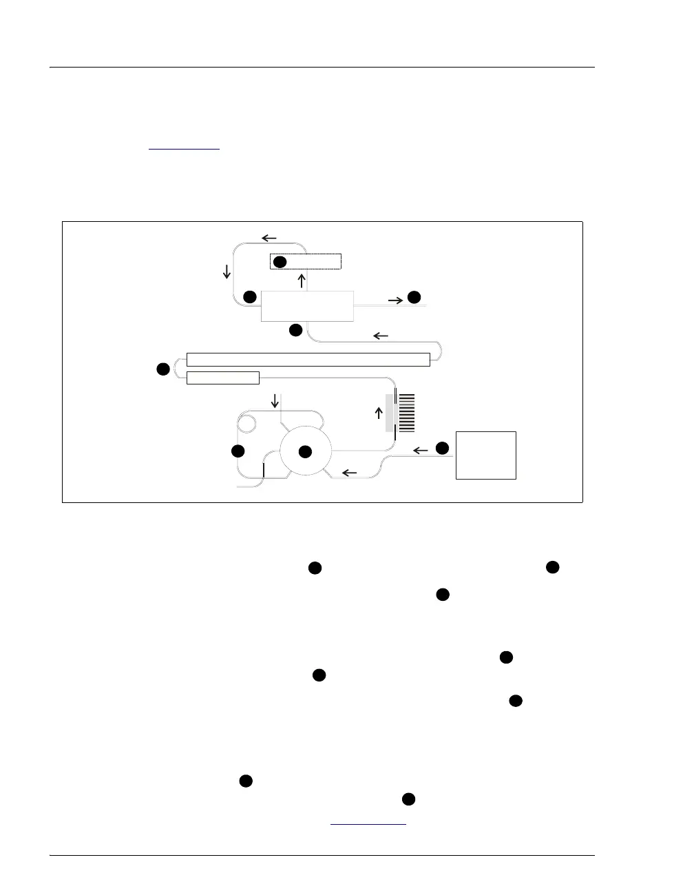
2.15.3 System Flow Schematic for Conductivity Detection
Figure 2-21 illustrates the flow path through a DC for a conductivity
detection application using suppression in recycle mode. For information
about other suppression modes, refer to the suppressor manuals. The
manuals are on the Dionex Reference Library CD-ROM (P/N 053891).
• Eluent from the pump or EG flows into the injection valve .
• After sample is loaded into the sample loop and the injection valve
is toggled to the Inject position, eluent passes through the loop.
• The eluent/sample mixture is pumped first through a temperature
stabilizer, then on to the guard and separator columns , and then
through the suppressor .
• From the suppressor, the mixture flows through the cell , where the
analytes are detected. A digital signal is sent to Chromeleon or
Chromeleon Xpress software.
• Finally, the mixture flows out of the cell and is recycled back into the
suppressor , where it is used as the water source for the regenerant
chamber. Flow is then routed to waste . If an EG is installed, flow is
routed to the CR-TC (see Section 2.10
for details).
Figure 2-21. DC Flow Schematic for Conductivity Detection
(Suppression in Recycle Mode)
ELUENT
TEMPERATURE
STABILIZER
CELLCOND
SUPPRESSOR
OUT
IN
PUMP or
ELUENT
GENERATOR
GUARD
SEPARATOR COLUMN
VALVE
1
2
3
4
5
6
WA
TE
SAMPLE
5
8
L
P
C
L
S
W
4
5
1
2
3
7
6
8
1
2
3
4
5
6
7
8