ICS-3000 Ion Chromatography System
24 Doc. 065031-04 1/08
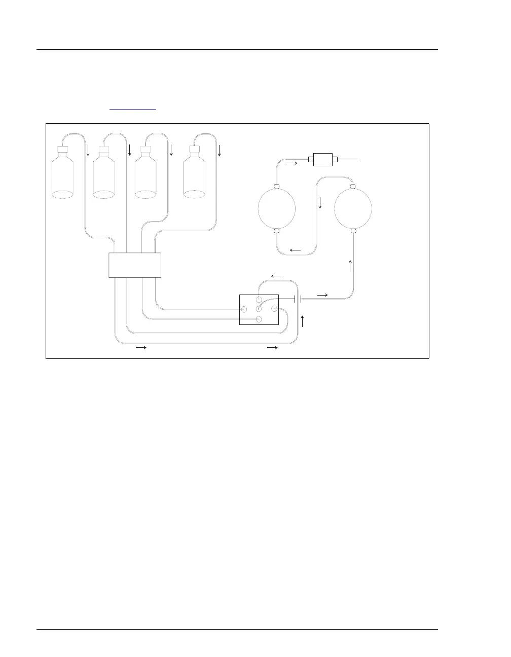
2.3.2 Gradient Pump Flow Schematic
Figure 2-5 illustrates the liquid flow path through a gradient pump.
• Eluent flows from the reservoirs and through the vacuum degas
chambers. The selected proportions of eluent flow out of the
proportioning valve assembly and into the inlet check valve on the
primary pump head.
• The inlet check valve opens, drawing eluent into the primary pump
head. At the same time, the secondary piston pushes forward, pushing
eluent into the system. After completing the intake, the primary
piston pushes eluent through the outlet check valve and into the
secondary pump head.
• Flow exits the secondary pump head, continues through the static
mixer, and is then directed to the remainder of the chromatography
system (the injection valve, columns, and detector).
Figure 2-5. Gradient Pump Flow Schematic
INLET
CHECK VALVE
PROPORTIONING
VALVE
OUTLET
CHECK VALVE
PUMP
HEAD
PUMP
HEAD
STATIC
MIXER
A
B
C
D
TO INJECTION VALV
ELUENT
A
ELUENT
B
ELUENT
C
ELUENT
D
VACUUM
DEGAS