ICS-3000 Ion Chromatography System
98 Doc. 065031-04 1/08
2.22 Injection Valves
The TC is available in the following configurations:
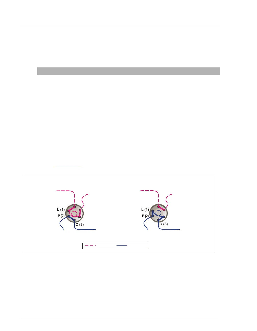
2.22.1 Injection Valve Operation
The 6-port injection valve has two operating positions: Load and Inject.
Liquid flows through either the Load or Inject path, depending on the
valve position.
Figure 2-55
shows flow schematics for the 6-port valve.
• In the Load position, sample is loaded into the sample loop, where it
is held until injection. Eluent flows from the pump, through the valve,
and to the column, bypassing the sample loop. Sample flows from the
syringe or autosampler line (if installed), through the valve, and into
the sample loop. Excess sample flows out to waste.
TC Description Part Number
TC with one 2-position, 6-port high-pressure injection valve 064660
TC with two 2-position, 6-port high-pressure injection valves 064661
TC with one 2-position, 6-port high-pressure injection valve and
one 2-position, 10-port high-pressure injection valve
(The 6-port valve is installed on the left side of the module.)
064651
TC with no injection valves 064659
Figure 2-55. TC Injection Valve Flow Schematics (6-Port Valve)
L (4)
S (5)
S (5)
W (6)
W (6)
To Waste
To Waste
Sample In
Sample In
To Column
To Column
From Pump
From Pump
L
AD P
ITI
N
INJECT POSITION
= Sample
= Eluent
L (4)