ICS-3000 Ion Chromatography System
312 Doc. 065031-04 1/08
9.23.4 Removing Trapped Air from the Conductivity Cell
Air bubbles in the cell can cause pulsations of the baseline, random noise,
and low readings. Air may result from outgassing of the eluent.
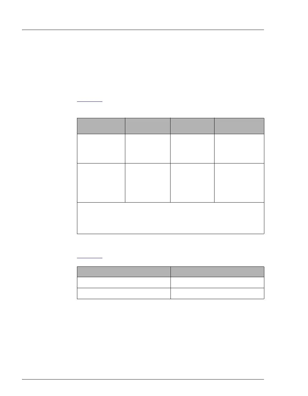
1. Connect enough backpressure tubing to the cell outlet to shrink
bubbles and allow them to pass more easily through the cell. Refer to
Table 9-2
for the appropriate type and number of backpressure tubing
coils required.
Table 9-3
lists the correct pressure range for each type of suppressor.
2. To verify that the required amount of backpressure is being generated,
follow the instructions in the flier, Backpressure Coil Pressure Test
for Dionex Suppressors (Document No. 031759), which is shipped
with the suppressor. The instructions are also in the suppressor
manual on the Dionex Reference Library CD-ROM (P/N 053891).
Suppressor
Type
Column
Format
Flow Rate
(mL/min)
Backpressure
Coils
AES 2-mm 0.25 to 0.50 2 red*
3-mm 0.50 to 1.00 2 red
4-mm 1.00 to 2.00 1 red
SRS or MMS 2-mm or 3-mm <0.25 2 red
2-mm or 3-mm 0.25 to 0.50 1 red
4-mm 0.50 to 1.50 2 black**
4-mm 1.50 to 3.00 1 black
*The red coil (P/N 045878) consists of 0.125-mm (0.005-in) ID PEEK
tubing with fittings.
**The black coil (P/N 045877) consists of 0.25-mm (0.010-in) ID PEEK
tubing with fittings.
Table 9-2. Backpressure Coil Requirements
Suppressor Type Pressure Range
AES 0.14 to 0.70 MPa (20 to 100 psi)
SRS or MMS ≤ 0.28 MPa (40 psi)
Table 9-3. Suppressor Operating Pressure Ranges