ICS-3000 Ion Chromatography System
50 Doc. 065031-04 1/08
2.14 Injection Valves
One or two injection valves can be installed in the lower compartment of the DC.
The following models are available: 6-port (P/N 061961) and 10-port
(P/N 061962).
2.14.1 Injection Valve Operation
Each ICS-3000 Ion Chromatography System injection valve has two
operating positions: Load and Inject. Liquid flows through either the
Load or Inject path, depending on the valve position.
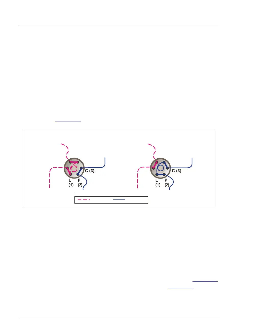
Figure 2-16
shows flow schematics for the 6-port valve.
• In the Load position, sample is loaded into the sample loop, where it
is held until injection. Eluent flows from the pump, through the valve,
and to the column, bypassing the sample loop. Sample flows from the
syringe or autosampler line (if installed), through the valve, and into
the sample loop. Excess sample flows out to waste.
• In the Inject position, sample is swept to the column for analysis.
Eluent flows from the pump, through the sample loop, and on to the
column, carrying the contents of the sample loop with it. Section 5.3
describes how to inject samples manually and Section 5.2
describes
how to inject samples with an autosampler.
Figure 2-16. Injection Valve Flow Schematics (6-Port Valve)
L (4)(5) S
(6) W
To Waste
Sample In
To Column
From Pump
Sample
Loop
L
AD P
ITI
N
Sample In
Sample
Loop
INJE
T P
ITI
N
To Colum
= Sample
= Eluent
To Waste From Pump
L (4)(5) S
(6) W