2 • DC Description
Doc. 065031-04 1/08 51
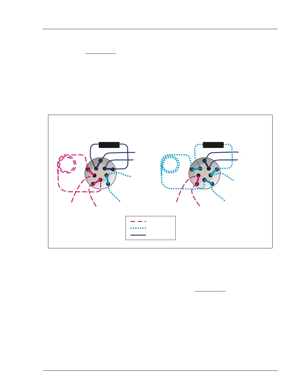
Figure 2-17 shows example flow schematics for the 10-port valve when it
is connected for an application that uses a concentrator column.
NOTE Other plumbing configurations for the 10-port valve
are possible, depending on the components to be
connected to the valve and the application to be run.
Refer to the appropriate Dionex Application Note
for more information.
Liquid flows through either the Load or Inject path, depending on the
valve position. For the example shown in Figure 2-17
, the flow occurs as
follows:
• In the Load position, sample flows from the syringe or autosampler
line, through the valve, and into the sample loop. Excess sample
flows out to waste. Eluent flows from the eluent pump, through the
valve, through the concentrator column, and to the separator column.
If sample was previously loaded onto the concentrator column, it is
swept to the separator column for analysis.
Figure 2-17. Injection Valve Flow Schematics (10-Port Valve)
Example Connections: Large Loop to Concentrator
1
3
5
7
9
LOAD POSITION
(Loop Loading)
To Waste
Eluent
Pump In
To Column
Sample In
To Waste
Concentrator
Large
Loop
Carrier Pump In
INJECT POSITION
(Concentrator Loading)
To Waste
Eluent
Pump In
To Colum
Sample In
To Waste
Concentrator
Carrier Pump In
= Sample
= Carrier
= Eluent
Large
Loop
2
4
6
8
10
1
3
5
7
9
2
4
6
8
10