2 • DP/SP Description
Doc. 065031-04 1/08 23
2.3 DP/SP Flow Schematics
2.3.1 Isocratic Pump Flow Schematic
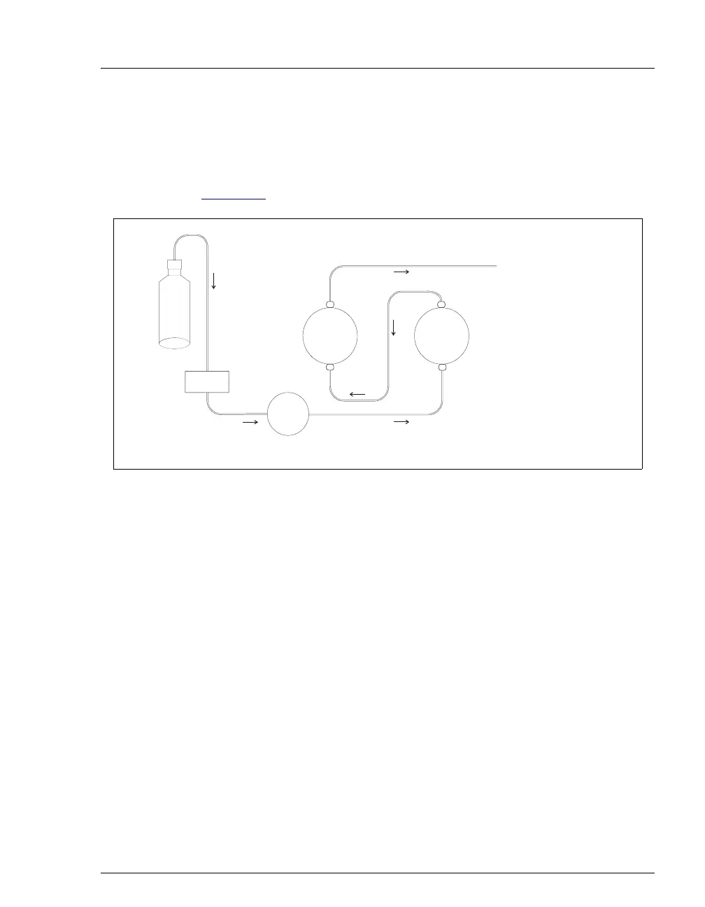
Figure 2-4 illustrates the liquid flow path through an isocratic pump.
• Eluent flows from the reservoir, through the vacuum degas chamber
(if the vacuum degas module is installed), through the eluent supply
on/off valve, and into the inlet check valve on the primary pump head.
• The inlet check valve opens, drawing eluent into the primary pump
head. At the same time, the secondary piston pushes forward, pushing
eluent into the system. After completing the intake, the primary
piston pushes eluent through the outlet check valve and into the
secondary pump head.
• Flow exits the secondary pump head and is directed to the remainder
of the chromatography system (the injection valve, columns, and
detector).
Figure 2-4. Isocratic Pump Flow Schematic
INLET
CHECK VALVE
OUTLET
CHECK VALVE
PUMP
HEAD
ELUENT SUPPLY
N
FF VALVE
PUMP
HEAD
TO INJECTION VALV
ELUENT
VACUUM
DEGAS