3 • Configurations
Doc. 065031-04 1/08 109
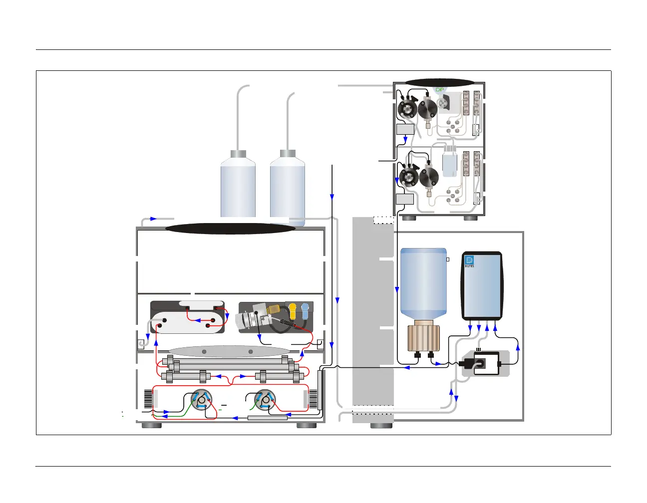
Figure 3-4. RFIC Dual System with CD and ED
To pump #2 inlet via the pump rear chase
To pump #1 inlet via the pump rear chase
Pump (front view)
EG
(left side view)
To waste
EGC
IN
OUT
System #1
System #1
System #2
DC (front view)
(1)
L
L
S
W
P
C
(2)
(3)
(4)(5)
(6)
(1)
L
L
S
W
P
C
(2)
(3)
(4)(5)
(6)
CR-TC
Eluent
Eluent
In
Out
Regen
Out
Regen In
From AS
From suppressor #1 Regen Out via the DC rear chase
Eluent
In
Eluent
Out
Regen
In
Regen
Out
AB
CD
A
B
C
D
AB
CD
A
B
C
D
To waste
Mixing
Chamber
To waste
Mixing
Chamber
Seal
Wash
Pump
Eluent In Regen In
Regen Out Eluent Out
Cell In
Cell Out
To waste
System #1
System #2
Temp.
Stabilizer
To AS/Waste
From AS
To AS/Waste
To inject valve #2 port P (2)
Temp.
Stabilizer
Separator #2
Separator #1
Guard #2 Guard #1
RFIC
Eluent Degasser
Deionized
Water
Mixer
Mixer
Backpressure Device
Backpressure Device
Eluent
Piston
Seal
Wash
(pump not to scale)
To the CR-TC Regen In via the EG rear chase