2
2-2
Connectrix DS-32M2 User Guide
Operating the Switch
Power Procedures
Power the Switch On
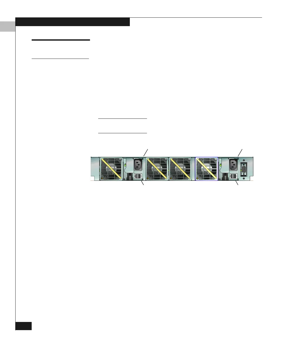
There are two AC power switches in the rear of the switch. Each
power switch is to the right of each AC power connector. (Refer to
Figure 2-1 on page 2-2.) Switch power on to the switch by pushing
each AC power switch up to the on position (1). When switching
power on, push the switch firmly to engage it. If the switch does not
engage properly because it was not pushed firmly enough, wait 30
seconds before attempting to switch power on again. Switch power
off by pushing the power switch in the opposite direction (0).
When pushing the switch off to cycle power, wait 30 seconds before pushing
the switch on again.
Figure 2-1 AC Power Switch Locations
Power-On Self-Tests When the power is switched on, power-on self tests (POSTs) run to
ensure correct operation of switch logic. These tests reside in flash
memory on the Control Processor (CTP). They verify correct
operation of the CTP, ports, LEDs, and other hardware components.
During POSTs, several tests occur in sequence. As they occur:
1. The green power (PWR) LED on the front panel illuminates.
2. The amber system error (ERR) LED on the front panel blinks
momentarily while the switch is tested.
3. The green LEDs at the top of the Ethernet connector blink while
the port is tested.
Receptacle
AC IN 1
Switch
Receptacle
Switch
AC IN 0