2
2-4
Connectrix DS-32M2 User Guide
Operating the Switch
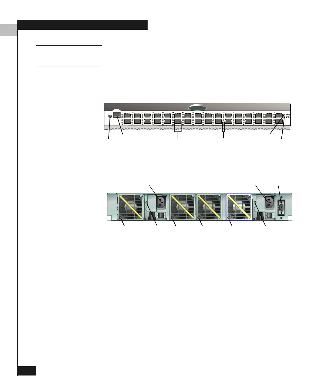
FRU LEDs and Connectors
LEDs
LEDs on hardware components indicate operational status.
Figure 2-2 and Figure 2-3 show LED locations and Table 2-1 describes
their functions.
Figure 2-2 Front Panel LEDs and Connectors
Figure 2-3 Rear Panel LEDs and Connectors
EMC
2
Power LED
Error LEDIML Button
Ethernet Connector
SFP Transceivers (32) Port LEDs (64)
LEDs:
Connectors:
Fan 3 Fan 2 Fan 1 Fan 0 PS 0PS 1
PS 1
Receptacle
PS 0
Receptacle
Maintenance
Port