4
Using the Hardware View
4-5
Monitoring and Managing the Switch
Operation Monitoring
Example
Determine hardware component operating status and states by the
simulated LED indicators and status symbols that appear on
hardware components. These simulated LEDs and alert symbols
reflect the state of the actual hardware as changes occur.
Corresponding or additional descriptions of hardware status and
states also display when you click on components to display
Properties windows.
Figure 4-1 illustrates the DS-32M2 Hardware view with examples of
symbols and LED indicators that can help you monitor hardware
operation. The numbers in circles are keyed to descriptions in
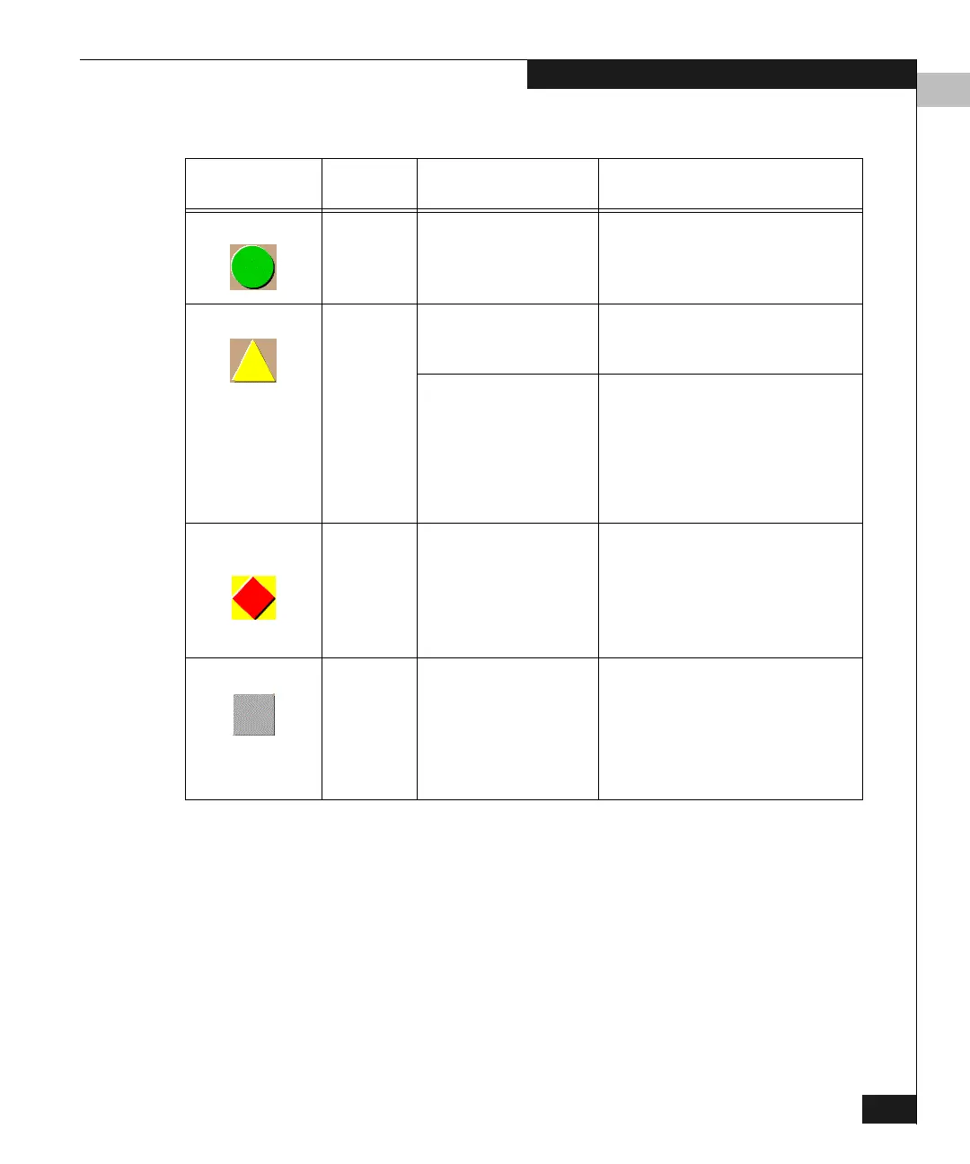
Table 4-1 Operating Status - Alert Panel and Switch Status
Alert Panel Symbol
Operator
Panel Text Switch Status Table Text Meaning
Green Circle: Online or
Offline
Fully Operational All components and installed ports are
operational; no failures.
Yellow Triangle: Degraded Redundant Failure A redundant component has failed, such
as a power supply, and the backup
component has taken over operation.
Minor Failure A failure occurred which has decreased
the switch operational ability. Normal
switching operations are not affected.
• One or more ports failed, but at least
one port is still operational.
• A fan has failed or is not rotating
sufficiently.
Red Diamond on
Yellow Background:
Failed NOT OPERATIONAL A critical failure prevents the switch from
performing fundamental switching
operations.
• All fans failed.
• All installed ports failed.
• Both power supplies failed.
Gray Square: N/A Never Connected
Link Timeout
Protocol Mismatch
Duplicate Session
Unknown Network Address
Incorrect Product Type
Switch status is unknown. This occurs if
the Ethernet network connection between
the Connectrix service processor and the
switch cannot be established or if the CTP
fails. Refer to No Link Status on page 4-3
for details on the status table text.