SP
+$02
+$06
+$08
+$0C
+$0E
+$10
15 0
STATUS REGISTER
! 0 0 1 J
SCAN PC
VECTOR OFFSET
PROGRAM C0gI~ITER
INTERNAL REGISTER
OPERATION WOR0
EFFECTIVE AOORESS
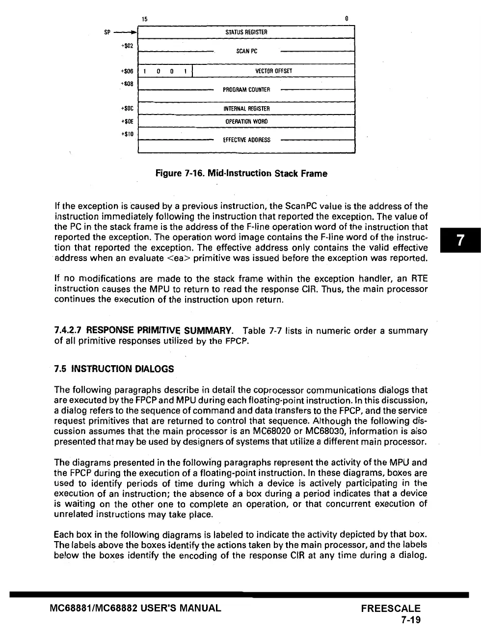
Figure 7-16. Mid-Instruction Stack Frame
If the exception is caused by a previous instruction, the ScanPC value is the address of the
instruction immediately following the instruction that reported the exception. The value of
the PC in the stack frame is the address of the F-line operation word of the instruction that
reported the exception. The operation word image contains the F-line word of the instruc-
tion that reported the exception. The effective address only contains the valid effective
address when an evaluate <ea> primitive was issued before the exception was reported.
If no modifications are made to the stack frame within the exception handler, an RTE
instruction causes the MPU to return to read the response CIR. Thus, the main processor
continues the execution of the instruction upon return.
7.4.2.7
RESPONSE PRIMITIVE SUMMARY. Table 7-7 lists in numeric order a summary
of all primitive responses utilized by the FPCP.
7.5 INSTRUCTION DIALOGS
The following paragraphs describe in detail the coprocessor communications dialogs that
are executed by the FPCP and MPU during each floating-point instruction. In this discussion,
a dialog refers to the sequence of command and data transfers to the FPCP, and the service
request primitives that are returned to control that sequence. Although the following dis-
cussion assumes that the main processor is an MC68020 or MC68030, information is also
presented that may be used by designers of systems that utilize a different main processor.
The diagrams presented in the following paragraphs represent the activity of the MPU and
the FPCP during the execution of a floating-point instruction. In these diagrams, boxes are
used to identify periods of time during which a device is actively participating in the
execution of an instruction; the absence of a box during a period indicates that a device
is waiting on the other one to complete an operation, or that concurrent execution of
unrelated instructions may take place.
Each box in the following diagrams is labeled to indicate the activity depicted by that box.
The labelsabove the boxes identify the actions taken by the main processor, and the labels
below the boxes identify the encoding of the response CIR at any time during a dialog.
MC68881/MC68882 USER'S MANUAL
FREESCALE
7-19