10
MOST SIGNIFICANT BIT OF BYTE
I
LEAST SIGNIFICANT B~T OF BYTE
,l I
24 23 16 15
MOST SIGNIFICANT I MIOOLE MOST
BYTE I SIGNIFICANT BYTE.
8 7
MIDDLE LEAST
SIGNIFICANT BYTE
LEAST SIGNifICANT
BY'R
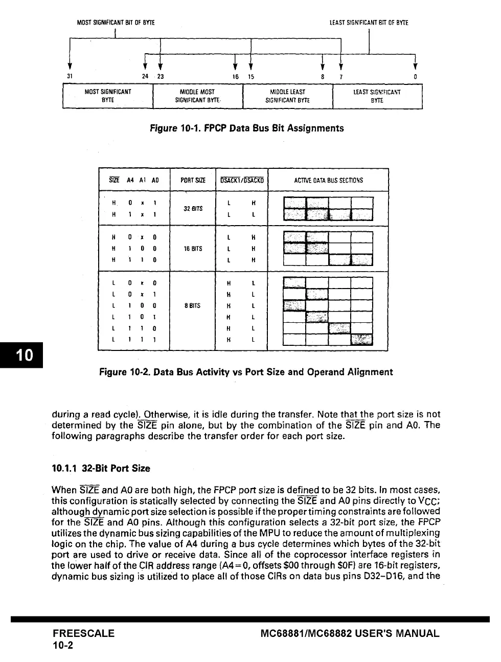
Figure 10-1. FPCP Data Bus Bit Assignments
I
¥
0
I
A4 AI AO PORTSJZE b"~"C'K~/D-'~"C'KO ACT[VEOATABUSSECllONS
H 0 x 1 L H
32 BITS
H 1 x 1 L L
H 0 x 0 L H : ~-~
H 1 1 0 L H ,= ~]~:: - 1
L 0 x O
L 0 x 1
L 1 0 0
L 1 0 1
L ! 1 0
L 1 1 1
8 BITS
H L
H L
H L
H L
H L
H L
i
Figure 10-2. Data Bus Activity vs Port Size and Operand Alignment
during a read cycle). Otherwise, it is idle during the transfer. Note that the port size is not
determined by the SIZE pin alone, but by the combination of the SIZE pin and A0. The
following paragraphs describe the transfer order for each port size.
10.1.1 32-Bit Port Size
When SIZE and A0 are both high, the FPCP port size is defined to be 32 bits. In most cases,
this configuration is statically selected by connecting the SIZE and A0 pins directly to VCC;
although dynamic port size selection is possible if the proper timing constraints are followed
for the SIZE and A0 pins. Although this configuration selects a 32-bit port size, the FPCP
utilizes the dynamic bus sizing capabilities of the MPU to reduce the amount of multiplexing
logic on the chip. The value of A4 during a bus cycle determines which bytes of the 32-bit
port are used to drive or receive data. Since all of the coprocessor interface registers in
the lower half of the CIR address range (A4= 0, offsets $00 through $0F) are 16-bit registers,
dynamic bus sizing is utilized to place all of those CIRs on data bus pins D32-D16, and the
FREESCALE
10-2
MC68881/MC68882 USER'S MANUAL