11
11.1.2 16-Bit Data Bus Coprocessor Connection
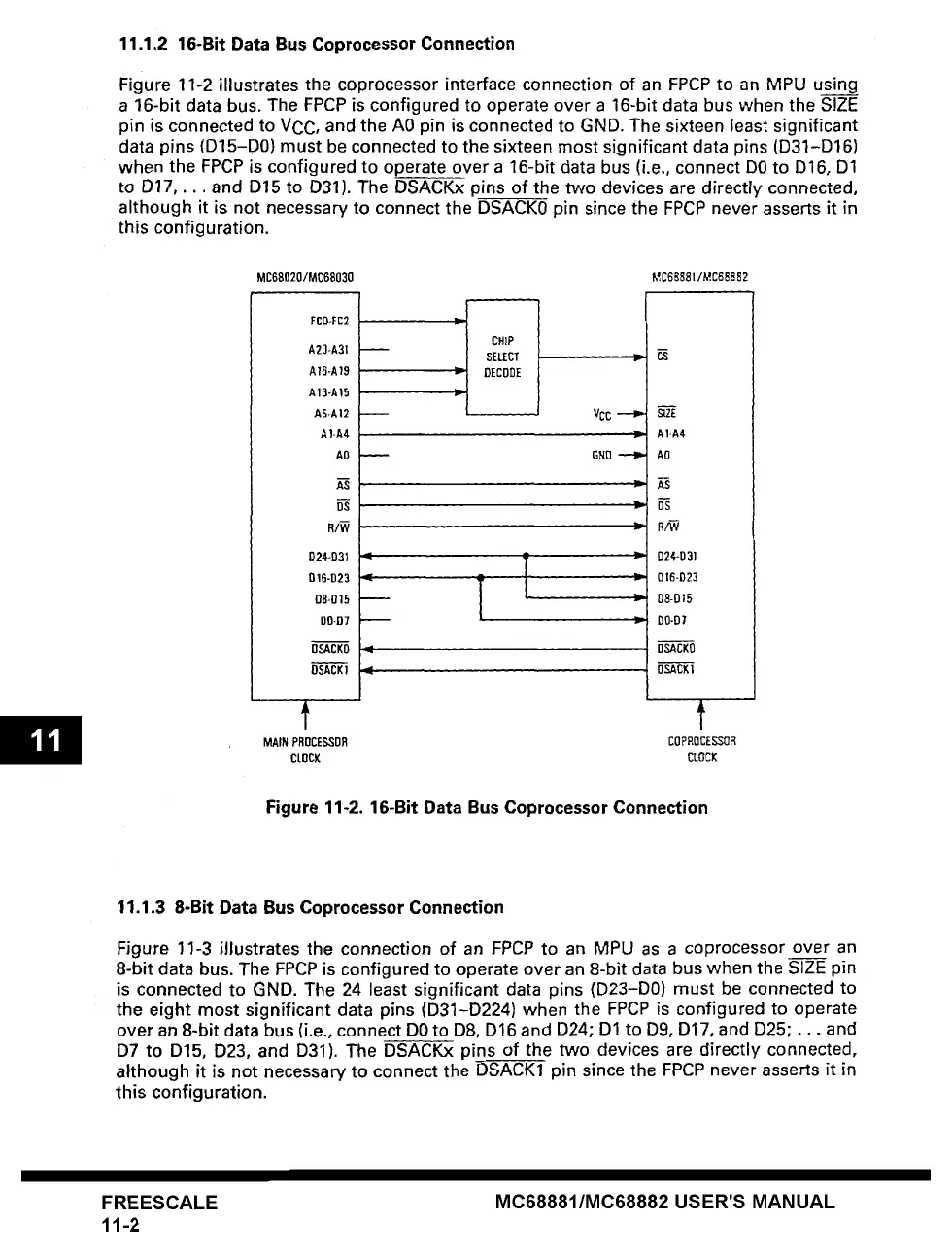
Figure 11-2 illustrates the coprocessor interface connection of an FPCP to an MPU using
a
16-bit data bus. The FPCP is configured to operate over a 16-bit data bus when the SIZE
pin is connected to VCC, and the A0 pin is connected to GND. The sixteen least significant
data pins (D15-D0) must be connected to the sixteen most significant data pins (D31-D16)
when the FPCP is configured to operate over a 16-bit data bus (i.e., connect DO to D16, D1
to D17 .... and D15 to D31). The DSACKx pins of the two devices are directly connected,
although it is not necessary to connect the DSACK0 pin since the FPCP never asserts it in
this
configuration.
MCBS020/MC68030 MC66881/MC688~2
FCO-FC2
A2D-A31
A16-A19
A13-AI5
AB-A12 •
A1-A4
AO -
D24-D31
D16-D23
OB-015
DO-D7
OSACKO
DSACK]
j---
- I CHIP
-L____
VCC
GND
]z=
~ZE
A1-A4
AO
R/W
D24-D31
016-D23
08-D15
D0-07
DSACKO
DSACKI
f t
MAIN PROCESSDR COPROCESSOR
CLOCK CLOCK
Figure 11-2. 16-Bit Data Bus Coprocessor Connection
11.1.3 8-Bit Data Bus Coprocessor Connection
Figure 11-3 illustrates the connection of an FPCP to an MPU as a coprocessor over an
8-bit data bus. The FPCP is configured to operate over an 8-bit data bus when the SIZE pin
is
connected to GND. The 24 least significant data pins (D23-D0) must be connected to
the eight most significant data pins (D31-D224) when the FPCP is configured to operate
over an 8-bit data bus (i.e., connect DO to D8, D16 and D24; D1 to D9, D17, and D25;... and
D7 to D15, D23, and D31). The DSACKx pins of the two devices are directly connected,
although it is not necessary to connect the DSACK1 pin since the FPCP never asserts it in
this configuration.
FREESCALE
11-2
MC68881/MC68882 USER'S MANUAL