12.5 AC ELECTRICAL CHARACTERISTICS -- CLOCK INPUT
(Vcc = 5.0 Vdc-+ 5%; GND = 0 Vdc, T A = O°C to 70°C) (see Figure 12-1 )
Num
1
2,3
4,5
Characteristic
Frequency of Operation
Cycle Time
Clock Pulse Width (Measured from 1.5 V to
1.5 V for 33 MHz}
Rise and Fall Times
16,67 MHz 20 MHz 25 MHz 33.33 MHz
Min Max Min Max Min Max Min Max
8 16.67 12.5 20 12.5 25 16.7 33.33
60 125 50 80 40 80 30 60
24 95 20 54 15 59 14 66
Unit
MHz
ns
ns
-- 5 -- 5 -- 4 -- 3 ns
CLOCK
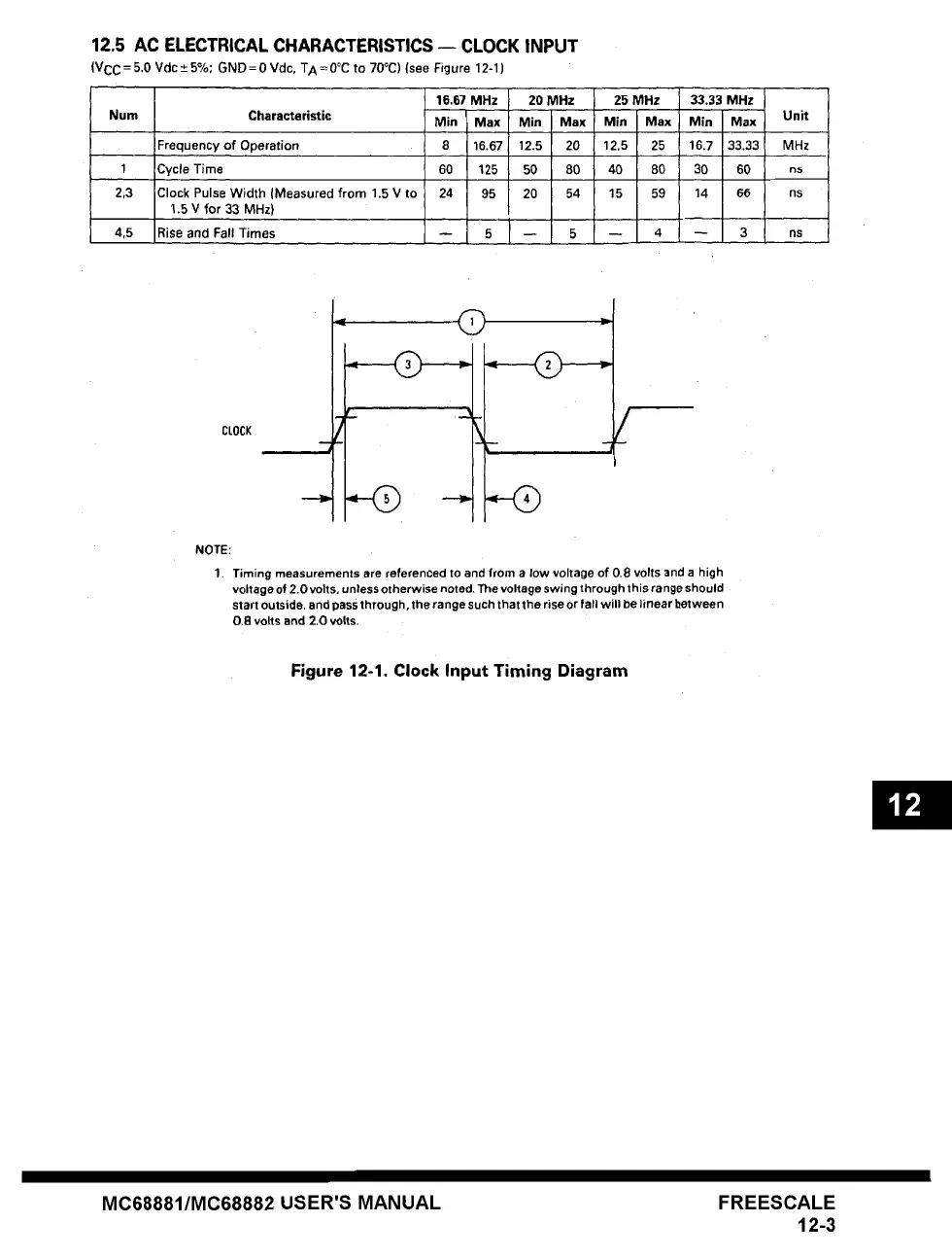
NOTE:
1. Timing measurements are referenced to and from a low voltage of 0.8 volts and a high
voltage of 2.0 volts, unless otherwise noted. The voltage swing through this range should
start outside, and pass through, the range such that the rise or fall will be linear between
0.8 volts and 2.0 volts.
Figure 12-1, Clock Input Timing Diagram
MC68881/MC68882 USER'S MANUAL FREESCALE
12-3