8
Table 8-18 indicates the number of clock cycles that should be added in the calculation of
the execution time for an arithmetic instruction (both the total and the overlap allowed
numbers) to account for the various rounding precision and exception handling combi-
nations. The entries in the table include the time from the end of the calculation phase to
completion of the FPCP instruction execution (i.e., when the PF bit in the null (CA=0)
primitive is clear if the response CIR is read).
When an FMOVE instruction that moves data between FP registers is executed in the
MC68882 and the FPCR mode control byte specifies single or double precision rounding,
no instruction execution concurrency is allowed. Similarly, an FMOVE instruction that
moves data to a single or double precision memory location executes without overlap in
the MC68882.
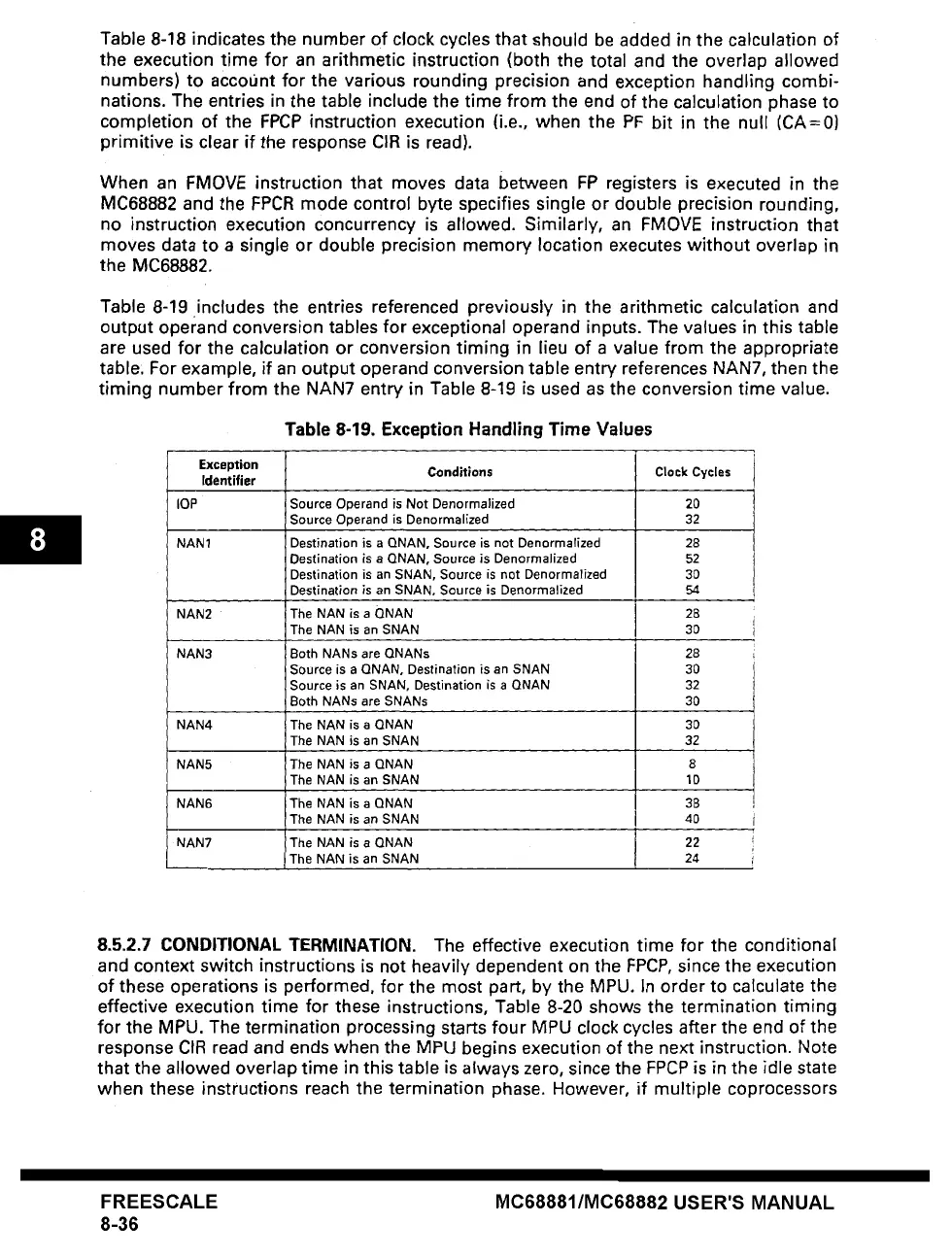
Table 8-19 includes the entries referenced previously in the arithmetic calculation and
output operand conversion tables for exceptional operand inputs. The values in this table
are used for the calculation or conversion timing in lieu of a value from the appropriate
table: For example, if an output operand conversion table entry references NAN7, then the
timing number from the NAN7 entry in Table 8-19 is used as the conversion time value.
Table 8-19. Exception Handling Time Values
Exception
Identifier
lOP
NAN 1
NAN2
NAN3
NAN4
NAN5
NAN6
NAN7
Conditions
Source Operand is Not Denormalized
Source Operand is
Denormalized
Destination is
a QNAN,
Source is not Denormalized
Destination
is a QNAN,
Source is Denormalized
Destination is an SNAN, Source is not Denormalized
Destination is an SNAN, Source is Denormalized
The NAN is
a QNAN
The NAN is an
SNAN
Both NANs are
QNANs
Source is
a QNAN,
Destination is an
SNAN
Source is an SNAN, Destination is
a QNAN
Both NANs are
SNANs
The NAN is
a QNAN
The NAN is an
SNAN
The
NAN is a QNAN
The NAN is an
SNAN
The NAN is
a QNAN
The
NAN is an SNAN
The NAN is
a QNAN
The NAN is an
SNAN
Clock Cycles
20
32
28
52
30
54
28
30
28
30
32
30
30
32
8
10
38
40
22
24
8.5.2.7 CONDITIONAL TERMINATION. The effective execution time for the conditional
and context switch instructions is not heavily dependent on the FPCP, since the execution
of these operations is performed, for the most part, by the MPU. In order to calculate the
effective execution time for these instructions, Table 8-20 shows the termination timing
for the MPU. The termination processing starts four MPU clock cycles after the end of the
response CIR read and ends when the MPU begins execution of the next instruction. Note
that the allowed overlap time in this table is always zero, since the FPCP is in the idle state
when these instructions reach the termination phase. However, if multiple coprocessors
FREESCALE
8-36
MC68881/MC68882 USER'S MANUAL