SECTION 9
FUNCTIONAL SIGNAL DESCRIPTIONS
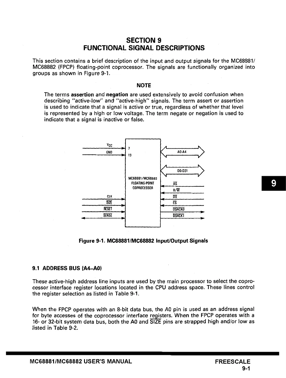
This section contains a brief description of the input and output signals for the MC68881/
MC68882 (FPCP) floating-point coprocessor. The signals are functionally organized into
groups as shown in Figure 9-1.
NOTE
The terms
assertion and negation
are used extensively to avoid confusion when
describing "active-low" and "active-high" signals. The term assert or assertion
is used to indicate that a signal is active or true, regardless of whether that level
is represented by a high or low voltage. The term negate or negation is used to
indicate that a signal is inactive or false.
VCC
GND
CLK
RESET
, •
7
13
MC68881/MC68882
FLOATING.POINT
COPROCESSOR
AO.A4 , >
DOoD31
R/W
OSACKO
Figure 9-1. MC68881/MC68882 Input/Output Signals
9.1 ADDRESS BUS (A4--A0)
These active-high address line inputs are used by the main processor to select the copro-
cessor interface register locations located in the CPU address space. These lines control
the register selection as listed in Table 9-1.
When the FPCP operates with an 8-bit data bus, the A0 pin is used as an address signal
for byte accesses of the coprocessor interface registers. When the FPCP operates with a
16- or 32-bit system data bus, both the A0 and SIZE pins are strapped high
and~or
low as
listed in Table 9-2.
MC68881/MC68882 USER'S MANUAL FREESCALE
9-1