8
The entries in the table for the return from exception (RTE) instruction include the time
from the beginning of the execution of the RTE by the MPU to the resumption of the
previously aborted operation. If the RTE instruction processes a pre-instruction frame, the
time in the table includes the time required to restore the processor context and prepare
to execute the instruction at the address in the stack frame program counter image. For
the mid-instruction frame, the time in the table includes the time required to restore the
processor context and read the response CIR to continue the previously suspended operation.
The
"RTE,
throwaway frame" entries include the time required to read and process the
throwaway stack frame (normally from the top of the interrupt stack) and then perform
RTE processing for the stack frame on top of the resulting active stack (normally either the
master or user stack). Thus, if the MPU must return from an interrupt that occurred while
the M bit in the MPU status register was set, a throwaway frame is first processed from
the interrupt stack, followed by the processing of the appropriate frame from the master
stack (which returns the processor to the context saved by the interrupt processing). For
such a case, the "RTE, throwaway frame" times are added to the RTE execution times for
the second stack frame to derive the overall execution times for the operation.
In addition to the occurrence of an exception, whether exceptions are enabled or not, can
also affect instruction execution time. This is because the FPCP requests the transfer of
the program counter at the start of any arithmetic instruction if any exception (other than
the BSUN exception) is enabled. If the source operand resides in a floating-point data
register, the transfer of the PC does not affect overall execution timing, since it takes place
concurrently with the execution of the operation by the FPCP. However, for source operands
external to the FPCP, the MPU first passes the PC, and then passes the operand; thus,
execution time is affected for this case.
8.6 MAIN PROCESSOR INSTRUCTION OVERLAP TIMING
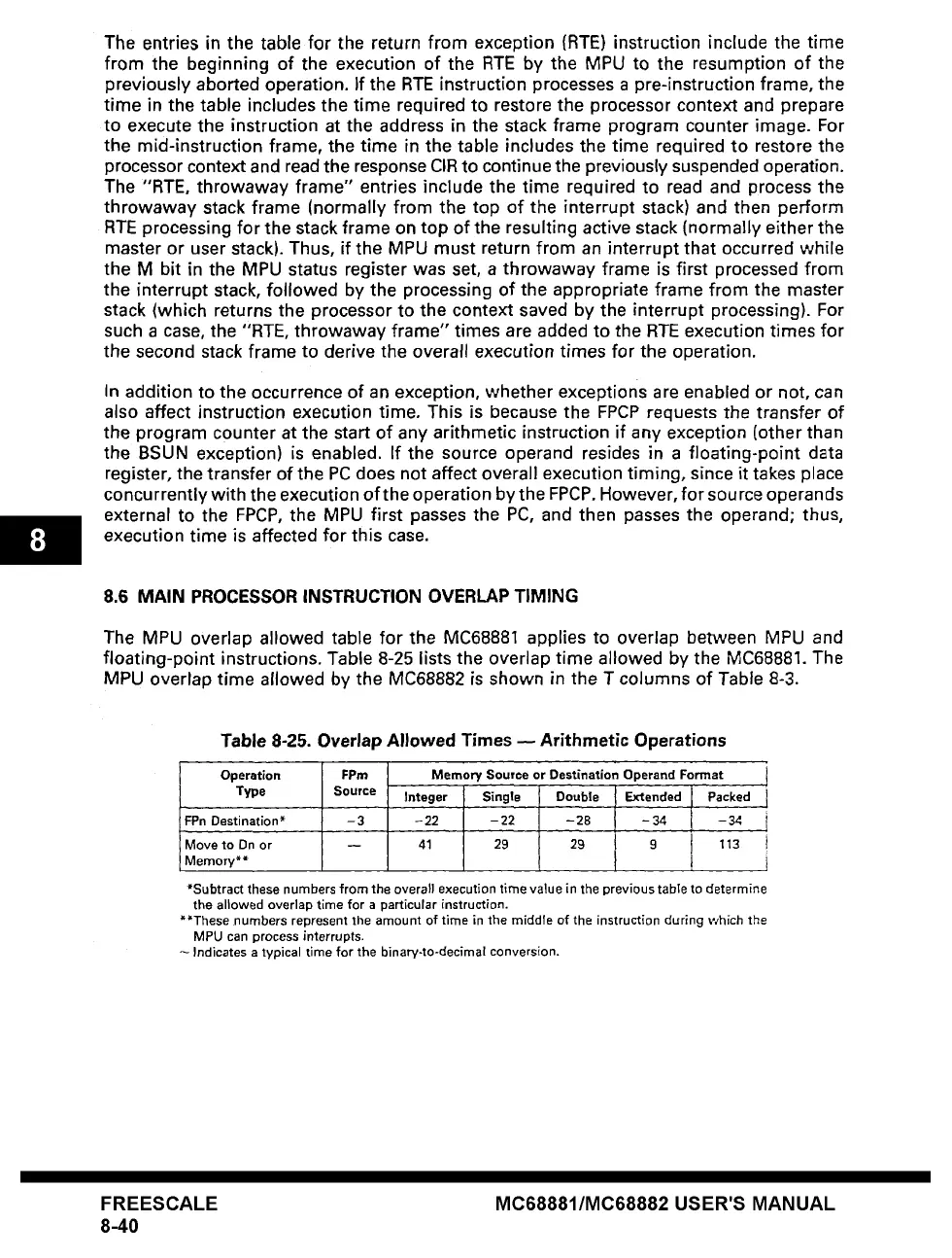
The MPU overlap allowed table for the MC68881 applies to overlap between MPU and
floating-point instructions. Table 8-25 lists the overlap time allowed by the MC68881. The
MPU overlap time allowed by the MC68882 is shown in the T columns of Table 8-3.
FPn Destination*
Table 8-25. Overlap Allowed Times -- Arithmetic Operations
Operation FPm Memory Source or Destination Operand Format
1
Type Source Integer
Single Double E~tended I
Packed
-3 -22 -22 -28 -34 1-34 i
Move to Dn or -- 41 29 29 9 113 i
Memory**
*Subtract these numbers from the overall execution time value in the previous table to determine
the allowed overlap time for a particular instruction.
**These numbers represent the amount of time in the middle of the instruction during which the
MPU can
process interrupts.
Indicates a typical time for the binary-to-decimal conversion.
FREESCALE
8-40
MC68881/MC68882 USER'S MANUAL