12
0JC is device related and cannot be influenced by the user. However, BCA is user de-
pendent and can be minimized by such thermal management techniques as heat sinks,
ambient air cooling, and thermal convention. Thus, good thermal management on the part
of the user can significantly reduce eCA so that BJA approximately equals eJC. Substitution
of BJC for BJA in equation (1) will result in a lower
semiconductor
junction
ter~perature.
Values for thermal resistance presented in this document, unless estimated, were derived
using the procedure described in Freescale Reliability Report 7843, "Thermal Resistance
Measurement Method for MC68XX Microcomponent Devices," and are provided for design
purposes only. Thermal measurements
are
complex and dependent on
procedure
and
setup. User derived values for thermal resistance may differ.
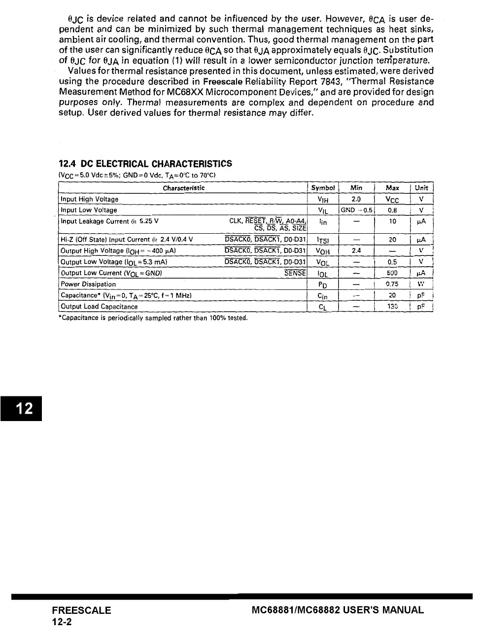
12,4 DC ELECTRICAL CHARACTERISTICS
(Vcc = 5.0 Vdc±5%; GND=0 Vdc, TA=0°C to 70°C)
symbol l Ms. I
Characteristic
Input High Voltage
VIH I 2.0 i
Input Low Voltage
VIE I GND -0.5 I
Input Leakage Current
(/~ 5.25 V CLK, RESE_ T, RNV,__A0-AA_~4, lin I --
CS, DS, AS, SIZE
J
Hi-Z (Off
State) Input Current
~( 2.4 V/0.4 V DSACK0, DSACK1, D0-D31
DSACK0, DSACK1, D0-D31
Output High Voltage
(IoH = -400 t~A)
DSACK0, DSACK1, D0-D31
Output Low Voltage
(IOL=5.3 mA)
Output Low Current
(VOL =
GND) SENSE
Power Dissipation
Capacitance*
(Vin=0, TA=25°C, f=l MHz)
Output Load Capacitance
*Capacitance is periodically sampled rather than
100%
tested.
|TSI ! --
VOH
I 2.4
,'OL I - l 0.5 I v
,OL
I
- I 5oo !~
vn i -- I 0.75 i v,'
I
cin
-- I 20 ~
p,~
CL -- i ~SO i pF
Max
I Unit
T
VCC
V
0.8 V
10
20 p.~
-- V
FREESCALE
12-2
MC68881/MC68882 USER'S MANUAL