9
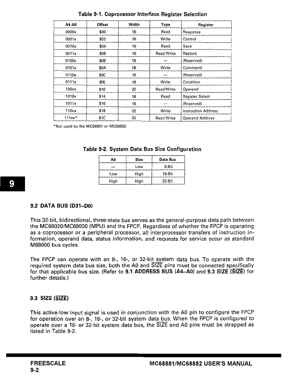
Table 9-1. Coprocessor Interface Register Selection
A4-A0
OOOOx
0001x
O01Ox
0011x
0100x
0101x
0110x
0111x
100xx
IOi~x
1011x
Offset
$0o
$02
$04
$06
$08
$OA
$0C
$OE
$I0
$14
$16
110xx $18
111××* $1C
*Not
used by the MC68881 orMC68882
Width
16
16
16
16
16
16
16
16
32
16
16
32
32
Type Register
Read Response
Write Control
Read Save
Read Write
Write
Write
ReadCVrite
Read
Write
Read Write
Restore
I
(Reserved)
Command
(Reserved)
Condition
Operand
Register Select
(Reservedl
Instruction Address
Operand Address
Table 9-2. System Data Bus Size Configuration
A0 Size Data Bus
-- Low 8-Bit
Low
High 16-Bit
High
High 32-Bit
9.2 DATA BUS (D31-D0J
This 32-bit, bidirectional, three-state bus serves as the general-purpose data path between
the MC68020/MC68030 (MPU) and the FPCP. Regardless of whether the FPCP is operating
as a coprocessor or a peripheral processor, all interprocessor transfers of instruction in-
formation, operand
data,
status information, and requests for service occur as standard
M68000 bus cycles.
The FPCP can operate with an 8-, 16-, or 32-bit system data bus. To operate with the
required system data bus size, both the A0 and SIZE pins must be connected specifically
for that applicable bus size. (Refer to 9.1 ADDRESS BUS (A4--A0) and 9.3 SIZE (SIZE) for
further details.)
9.3 SIZE (SIZE)
This active-low input signal is used in conjunction with the A0 pin to configure the FPCP
for operation over an 8-, 16-, or 32-bit system data bus. When the FPCP is configured to
operate over a 16- or 32-bit system data bus, the SIZE and A0 pins must be strapped as
listed in Table 9-2.
FREESCALE
9-2
MC68881/MC68882 USER'S MANUAL