4
Table 4-18. Encodings for Move Multiple FPn Operations
Mode Instruction Allowed
} MPU
Field Operation <ea> Modes i Services
Move Memory to Registers {dr=0)
00 (Invalid Operation) -- Note 1
01 (Invalid Operation) -- D,'ote 1
10 Move to Registers, Static Register List (An}+ or Control D,~ote 2
11 Move to Registers, Dynamic Register List (An) + or Control Note 3
Move Registers to Memory (dr = 1)
0O
Move from Registers, Static Register List
- (An) r~o:e 2
01 Move from Registers, Dyamic Register List -(An) h~cte 3
10 Move from Registers, Static Register List Control Alterabte t~o~e 2
11 Move from Registers, Dynamic Register List Control Alterebte t~ote 3
NOTES:
1. These encodings cause the FPCP to perform an operation that is inconsistent with the M68000 Family move multipTe
operations. For these cases, the selected registers are transferred in the order that is appropriate for the
predecrement
addressing mode (i.e., FPT-FP0) using a static or dynamic register list, respectively. However, the MPU does not a~;o~,,'
the predecrement addressing mode for a move from memory to multiple
coprocessor
registers operation. Thus, as-
semblers and compilers should not generate these encodings, or unexpected results me'( occur.
2. This instruction requires two primitives; the first is the transfer multiple coprocessor registers {CA=l) primitive to
request that the MPU evaluate the effective address, read the register select CIR, and transfer the number of regis',~rs
indicated
by the mask (with an operand size of 12 bytes for each register). The second primitive is null (CA=0), whi~'ch
is used to terminate the dialog.
3. This instruction requires three primitives; the first is the transfer single main processor register (CA=l) primitive to
request the transfer of the MPU data register that contains the dynamic register'list. The
second
is the transfer multipTe
coprocessor registers (CA= 1} primitive to request that the MPU evaluate the effective address, read the register seTe~
CIR, and transfer the number of
registers indicated by
the mask (with an operand size of 12 bytes for
each
regi~er).
The third primitive is null (CA=0) to terminate the dialog.
based on the floating-point condition codes as described in 4.4 CONDITIONAL TEST DEF-
INITIONS. The true or false result is returned to the main processor with the null primitive.
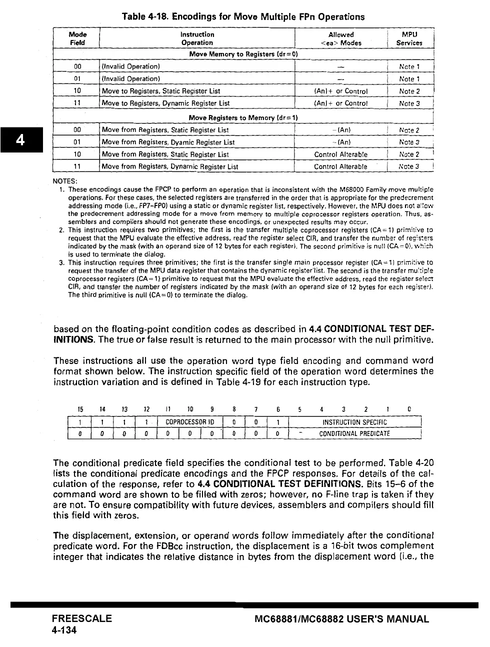
These instructions all use the operation word type field encoding and command word
format shown below. The instruction specific field of the operation word determines the
instruction variation and is defined in Table 4-19 for each instruction type.
f5 14 t3
12 11
~O 9 8 7 6
5 4 3 2 1 0
INSTRUCTION SPECIFIC I
- CDtYDtTt0NAL PREDICATE I
The conditional predicate field specifies the conditional test to be performed, Table 4-20
lists the conditional predicate encodings and the FPCP responses. For details of the cal-
culation of the response, refer to 4.4 CONDITIONAL TEST DEFINITIONS. Bits 15-6 of the
command word are shown to be filled with zeros; however, no F-line trap is taken if they
are not. To ensure compatibility with future devices, assemblers and compilers should fill
this field with zeros.
The displacement, extension, or operand words follow immediately after the conditional
predicate word. For the FDBcc instruction, the displacement is a 16-bit twos complement
integer that indicates the relative distance in bytes from the displacement word (i.e., the
FREESCALE
4-134
MC68881/MC68882 USER'S MANUAL