10
cycles per synchronous read cycle results in a small percentage change in the overall
execution time for an instruction (since most instructions typically require over 50 clock
cycles to execute). The only environment where these timing variances may be of concern
is when a programmer is attempting to optimize an instruction sequence for maximum
overlap. In this case, these factors should be added to the instruction execution timing
variability mechanisms discussed in SECTION 8 INSTRUCTION EXECUTION TIMING.
10.4.2 Asynchronous Read Cycles
When the main processor performs any access to the FPCP with R!W high other than a
read of the response or save CIR, the FPCP responds by executing an asynchronous read
cycle. In this context, the term asynchronous signifies that the bus cycle timing is not
related to the FPCP or MPU clock signals in any way. The FPCP supports this type of
operation by implementing all of the CIRs, except the response and save CIRs, as dual
ported structures. Thus, the main processor can access these CIRs at the maximum speed
regardless of the clock frequency of the FPCP, while the FPCP internally accesses these
CIRs in a synchronous manner.
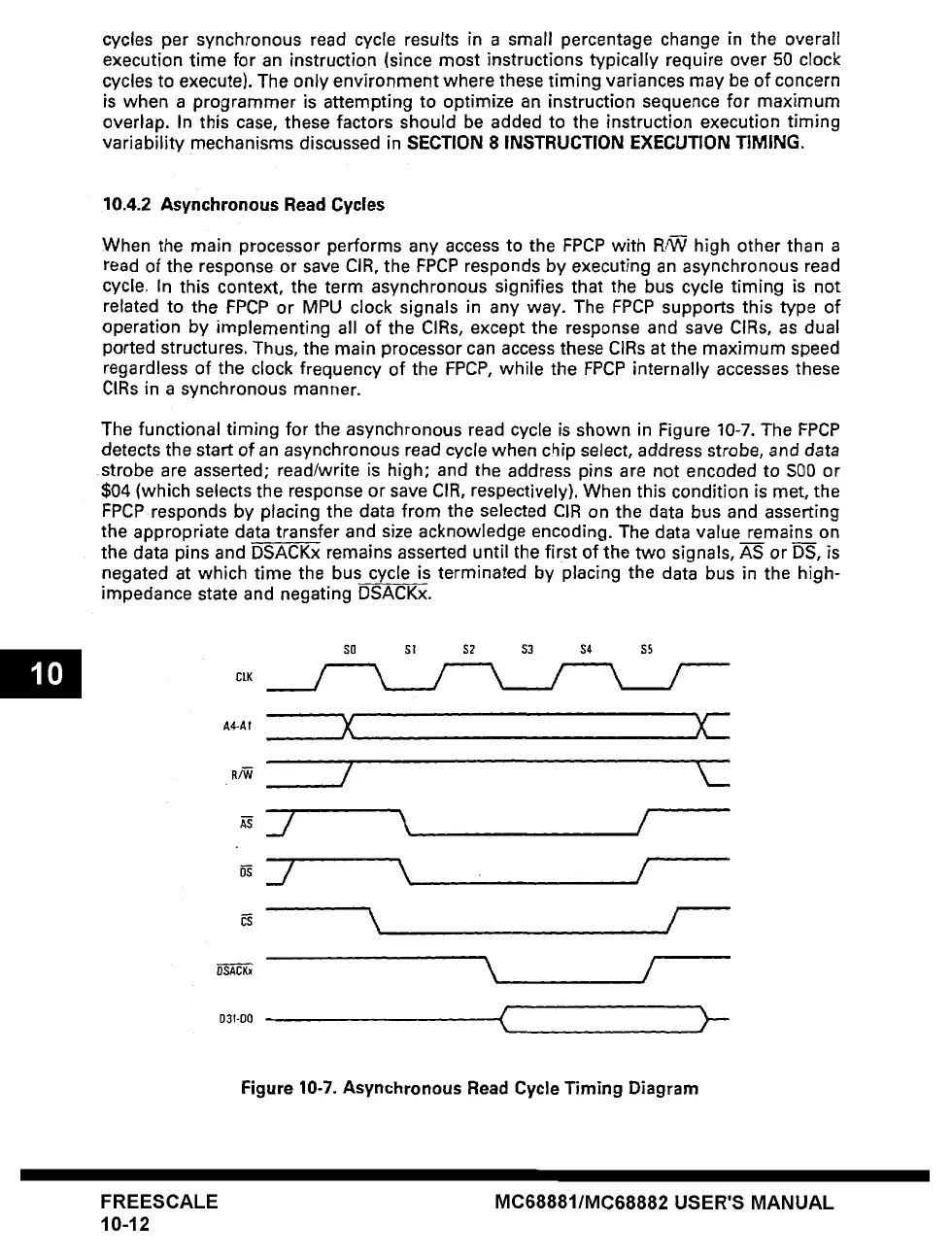
The functional timing for the asynchronous read cycle is shown in Figure 10-7. The FPCP
detects the
start
of an asynchronous read cycle when chip select, address strobe, and data
strobe are asserted; read/write is high; and the address pins are not encoded to SO0 or
$04 (which selects the response or save CIR, respectively). When this condition is met, the
FPCP responds by placing the data from the selected CIR on the data bus and asserting
the appropriate data transfer and size acknowledge encoding. The data value remains on
the data pins and DSACKx remains asserted until the first of the two signals, AS or DS, is
negated at which time the bus cycle is terminated by placing the data bus in the high-
impedance state and negating DSACKx.
CLK
A4-AI
g~
DSACKx
D3T-DO
SO S!
X
,/
$2 $3 $4 $5
/
)CZ
k__
_./ \ /
_/ \ I
\ /
\ /
<
.>-
Figure 10-7. Asynchronous Read Cycle Timing Diagram
FREESCALE
10-12
MC68881/MC68882 USER'S MANUAL