12.6 AC ELECTRICAL CHARACTERISTICS -- READ AND WRITE CYCLES (Continued)
16.67 HMz 20 MHz 25 MHz 33.33 MHz
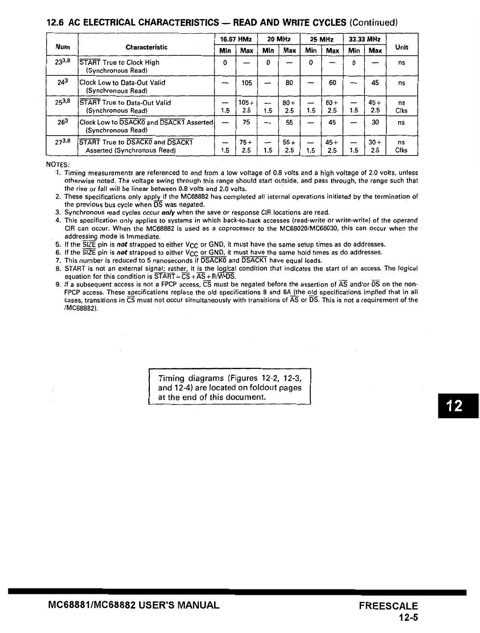
Num Characteristic Min Max Min Max Min Max Min Max Unit
233,8 START True to Clock High 0 -- 0 -- 0 -- 0 -- ns
(Synchronous Read)
243 Clock low to Data-Out Valid -- 105 -- 80 -- 60 -- 45 ns
(Synchronous Read)
253,8 START True to Data-Out Valid -- 105+ -- 80+ -- 60+ -- 45+ ns
(Synchronous Read) 1.5 2.5 1.5 2.5 1.5 2.5 1.5 2.5 Clks
263 Clock Low to DSACK0 and DSACK1 Asserte~ -- 75 -- 55 -- 45 -- 30 ns
(Synchronous Read)
273,8 START True to DSACK0 and DSACK1 -- 75+ -- 55+ -- 45+ -- 30+ ns
Asserted (Synchronous Read) 1.5 2.5 1.5 2.5 1.5 2.5 1.5 2.5 Clks
NOTES:
1. Timing measurements are referenced to and from a low voltage of 0.8 volts and a high voltage of 2.0 volts, unless
otherwise noted. The voltage swing through this range should start outside, and pass through, the range such that
the rise or fall will be )~near between 0.8 volts and 2.0 volts.
2. These specifications only appl _y if the MC68882 has completed all internal operations initiated by the termination of
the previous bus cycle when DS was negated.
3. Synchronous read
cycles occur only when the save or response CIR locations are read,
4. This specification only applies to systems in which back-to-back accesses (read-write or write-write) of the operand
CIR can occur. When the MC68882 is used as a coprocessor to the MC68020/MC68030, this
can occur when the
addressi~ mode is Immediate.
5, If the SIZE pin is
not strapped to either VCC or GND, it must have the same setup times as do addresses.
6. If the SIZE pin is
not strapped to either VCC or GND. it must have the same hold times as do addresses.
7. This number is reduced to 5 nanoseconds if DSACK0 and DSACK1 have equal loads.
8. START is not an external signal; rather, it is the
Iopical condition that indicates the start of an access. The logical
equation for this condition is START = CS + AS + RNV.DS.
9. If a subsequent access is not a FPCP access, CS must be negated before the assertion of A-S and/or D"S on the non-
FPCP access. These specifications replace the old specifications 8 and 8A (the old specifications implted that in al~
cases, transitions in CS must not occur simultaneously with transitions of AS or DS. This is not a requirement of the
/MC68882).
Timing diagrams (Figures 12-2, 12-3,
and 12-4) are located on foldout pages
at the end of this document.
MC68881/MC68882 USER'S MANUAL FREESCALE
12-5
 Loading...