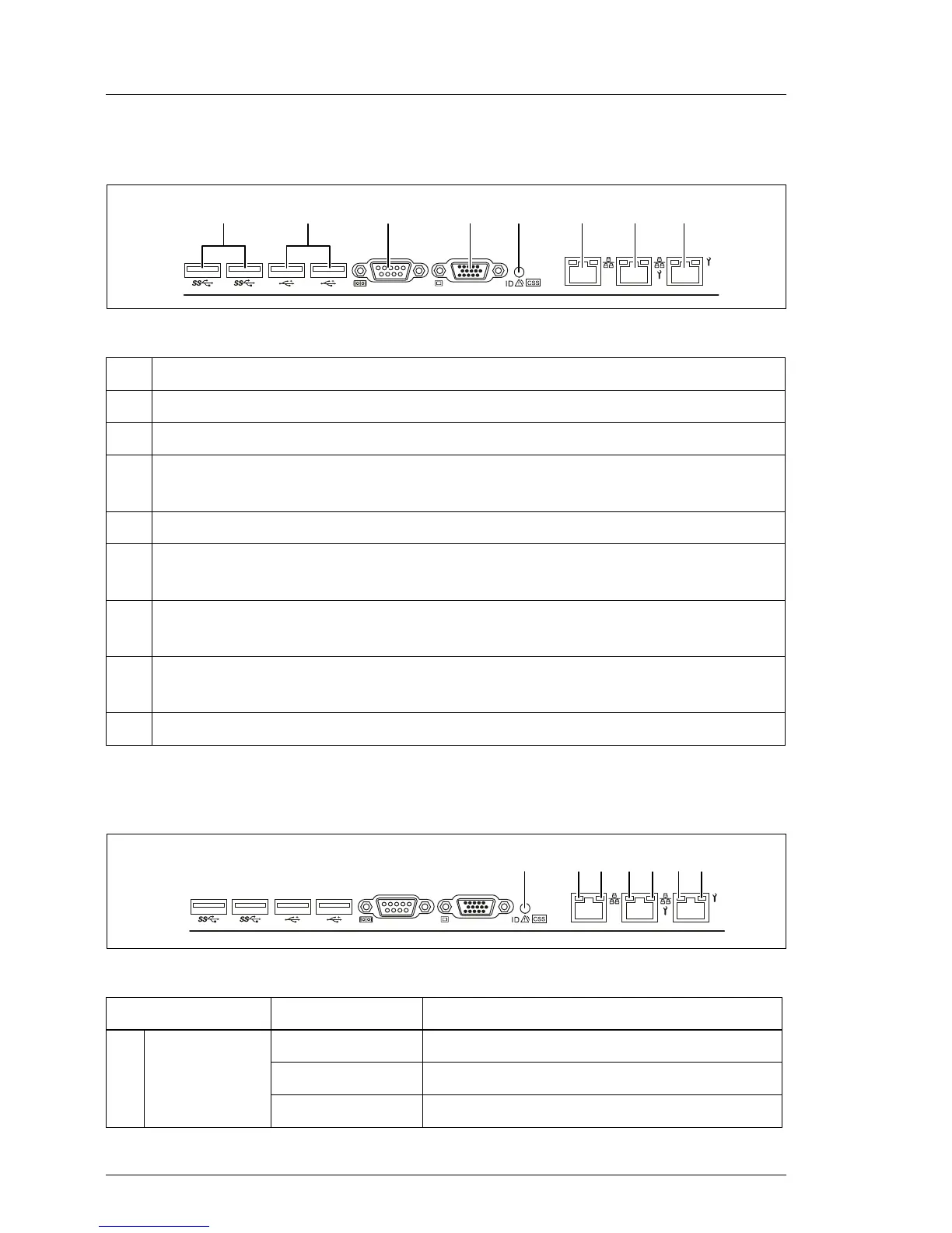
16.2.1.3 I/O panel connectors
Figure 226: Connector panel
16.2.1.4 I/O panel indicators
Figure 227: I/O panel indicators
No. Description
1 2x USB 3.0 connectors
2 2x USB 2.0 connectors
3 Serial connector COM1 (can be used as default interface or to
communicate with the iRMC S4)
4 Video connector (VGA)
5 Error indicator (orange), ID indicator (blue); (description see preceding
section)
6 Standard LAN connector; this connector is displayed in BIOS Setup
Utility and MAC address label as LAN1
7 Shared LAN connector (for WOL/PXE/iSCSI function); this connector is
displayed in BIOS Setup Utility and MAC address label as LAN2
8 Management LAN connector (for iRMC S4 server management function)
Indicator Status Description
1
Error
indicator
off no critical event
orange on prefailure detected
orange flashing component failure

 Loading...