Follow the test conditions described for respective test points shown in the table below.
Table 10-13 chassis leakage current test condition
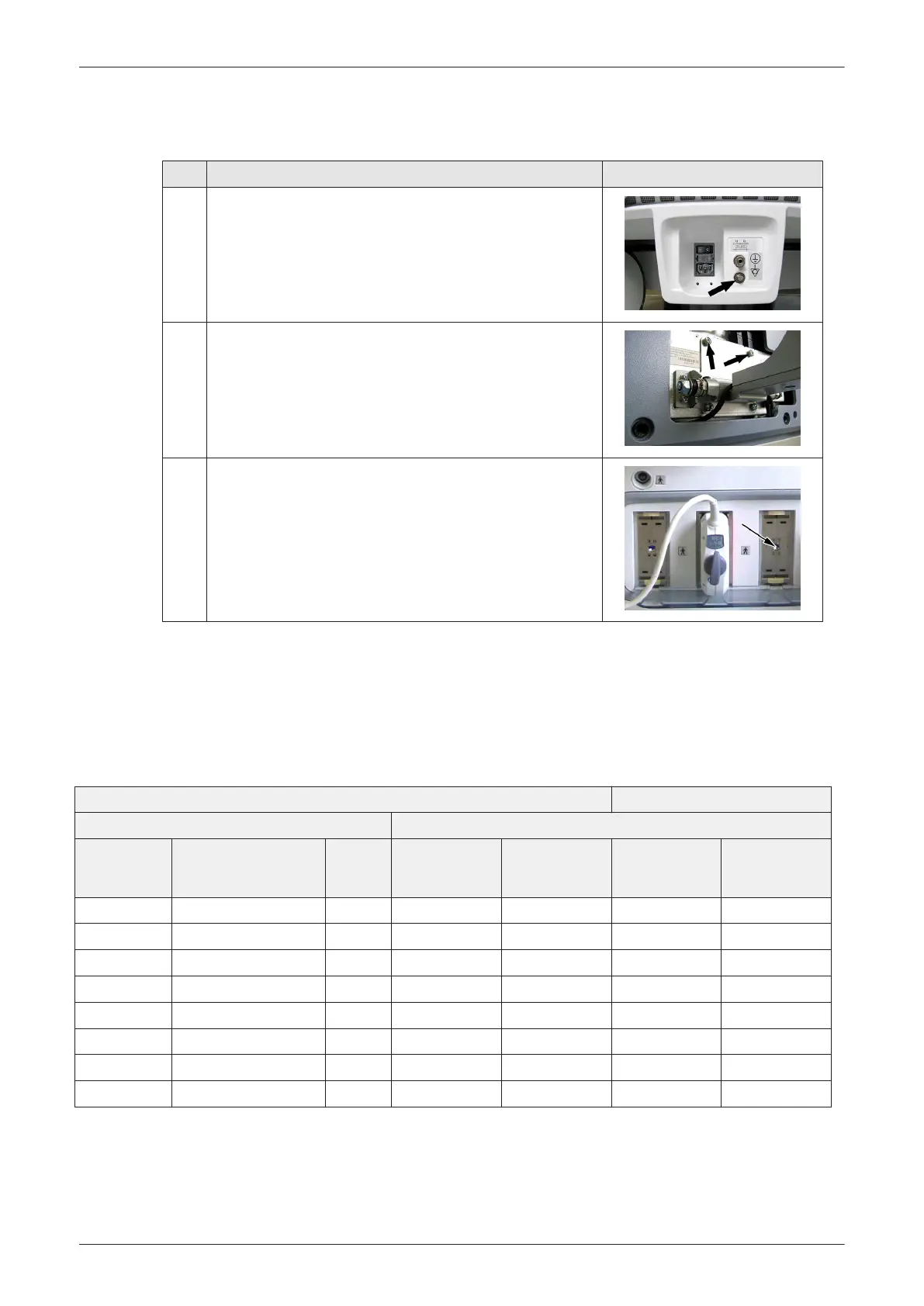
Test Condition Test Point (image)
1 Potential equilibrium connector (rear of system, on power supply
RSP)
2 Monitor housing (mounting screw for LCD Monitor housing, rear of
monitor)
3 Probe connector (probe mounting receptacle on front of system)
10.6.5.3 Data Sheet for Enclosure/Chassis Leakage Current
Table 10-14
shows a typical format for recording the enclosure/chassis leakage current. Measurements
should be recorded from multiple locations for each set of test conditions.
The actual location of the test probe may vary by system.
Record all data and keep the record of the results with other hard copies of maintenance data.
Table 10-14 Typical Data Format for recording Enclosure/Chassis Leakage Current
Unit under Test: Date of Test:
Test Conditions Measurement/Test Point Location
System Power Grounding/PE Limit μA
Potential
equilibrium
connector
Monitor housing Probe connector
off closed 100
off open 500
on closed 100
on open 500
off closed (reversed polarity) 100
off open (reversed polarity) 500
on closed (reversed polarity) 100
on open (reversed polarity) 500
Care and Maintenance
Voluson E-Series Service Manual
5539550APB Revision 6
10-15