Operation – Monitoring and Diagnosis
User Manual corpuls
3
96 ENG - Version 2.1 – P/N 04130.2
Warning
Additional use of a nerve stimulator may modify or completely suppress the
ECG representation. In some cases, the ECG of an implanted pacer is
displayed instead.
Warning
In patients with an implanted pacer, it is possible that shockable ECG rhythms
or arrhythmias will only be detected to a limited extent.
To check the ECG cables for functional readiness, the use ot the optionally
available ECG cable tester is recommended (see chapter 9.8 Approved
Accessories, Spare Parts and Consumables, p. 224).
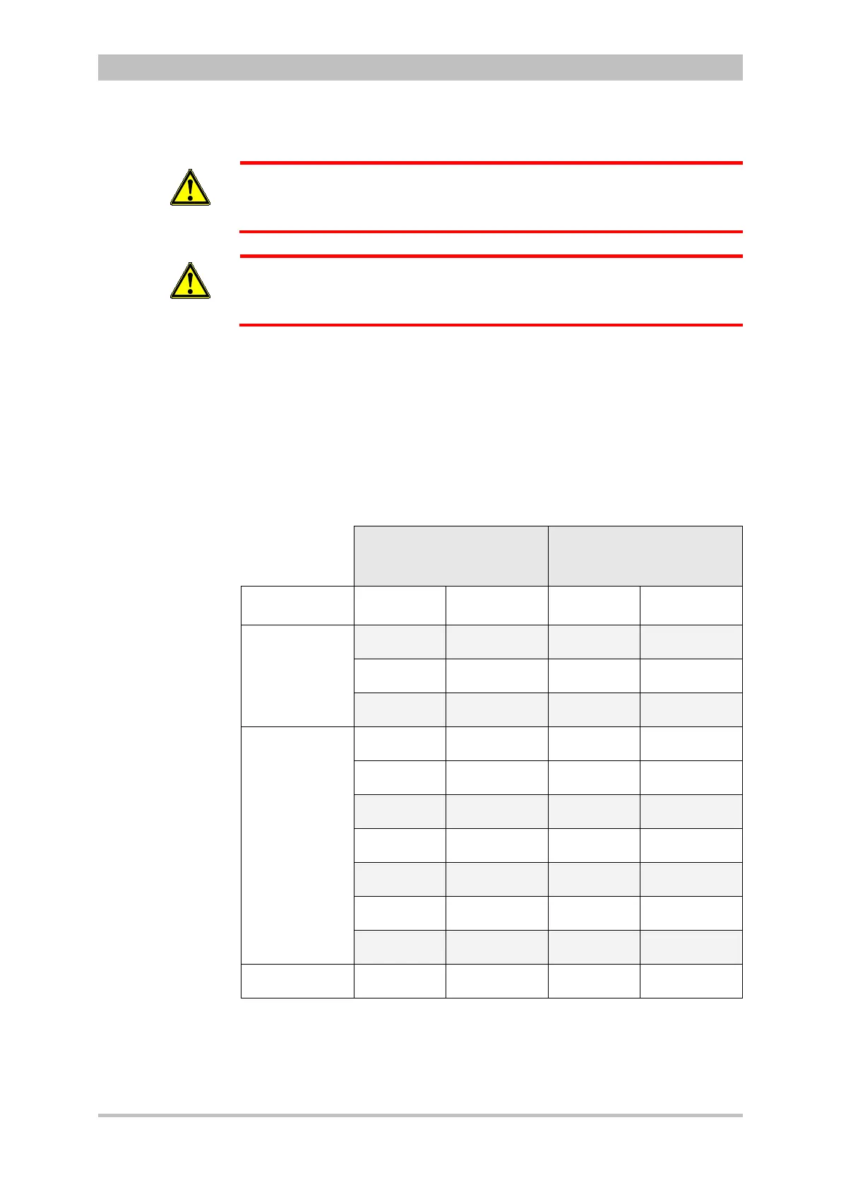
6.2.2 ECG Lead Colour Coding
According to DIN EN 60601-2-51, two codes apply for colour coding ECG lead
cables. As a rule, code 1 is generally used in the European region and code 2 in
the American region.
CODE 1
(conventionally used in the
European region)
CODE 2
(conventionally used in the
American region)
labelling
labelling
Extremities
(according to
Einthoven and
Goldberger)
R Red RA White
L Yellow LA Black
F Green LL Red
Chest wall
(according to
Wilson)
C White V Brown
C1 White/red V1 Brown/red
C2 White/yellow V2 Brown/yellow
C3 White/green V3 Brown/green
C4 White/brown V4 Brown/blue
C5 White/black V5 Brown/orange
C6 White/violet V6 Brown /violet
Neutral
N Black RL Green
Table 6-1 ECG lead colour coding
For all representations of the ECG leads in this operating manual see CODE 1
(conventionally used in Europe).