User Manual corpuls
3
General Operating Instructions
ENG - Version 2.1 – P/N 04130.2 35
4.1.2 Basic Structure of the Display Pages
on the Monitoring Unit
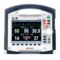
The display has the following structure:
Fig. 4-2 Monitoring unit, example of basic structure of the display pages
1 Status line
2 Parameter area
3 Curve and display area
4 Message line
5 Softkey line
The colours of the parameters and curves in the illustrations of this user manual
may differ from the actual display.
The following data are displayed in the status line (item 1):
• Physiological and technical alarms
• Patient’s name (editable)
• Time and deployment time alternating every 5 seconds
• Symbols for telemetry-functions
• State of charge of the batteries on mains operation
• Remaining running time of the device on battery operation
• Connection status of the modules
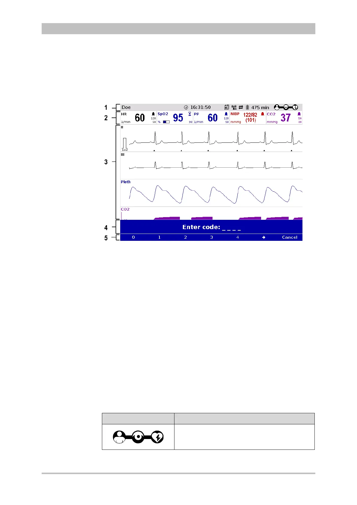
Connection status Meaning
All three components are connected mechanically
and communicate visually via an infrared
interface.